


Hi
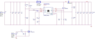
I designed the LM3488 circuit with reference to the web bench design.
As for the design conditions, the input was 3.5V to 4.2V, and the output was 12V/3A.
The switching frequency is about 370KHz, R sense=4m ohm, RsL=0 ohm is used.
The circuit is as follows. The test uses an electronic loader.
When there is no load, normal output voltage comes out, and the switching frequency is also normal.
However, when the output current is 150~200mA or more, the switching frequency is partially dropped, and if the current is further increased, the switching frequency is lowered to 16KHz.
At that time, the voltage of the compensation pin also exceeds 1.4V and rises to 2V or more.
It works normally in web bench simulation and Pspice simulation.
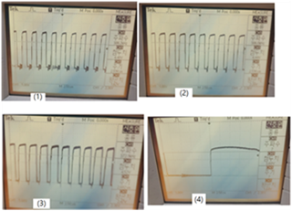
The test waveform is attached.
It is a test waveform with a load change.
1) At 0.2A load
2) At 0.3A load
3) At 0.4A load
4) When 0.5A or more
The switching frequency is 373KHz (R FA = 43K).
As the load current increases, the duty increases, but it is already over 70% at 0.4A load and the switching frequency is reduced by almost 8 times or more at 0.5A load. In other words, at this time, the voltage of the Comp pin becomes 2V or more, and it becomes an uncontrolled state.
Please review which part is problematic and which part should be checked.
Thanks.
