This thread has been locked.

If you have a related question, please click the "Ask a related question" button in the top right corner. The newly created question will be automatically linked to this question.

Not getting current below 50% using PWM driven TPS61080

Other Parts Discussed in Thread: TPS61080, TPA6205A1

Hello,

we are using the TPS61080 for PWM dimmed backlight control, but cannot get the current below ~60%. Can an experienced (TI) engineer look at what the problem might be?

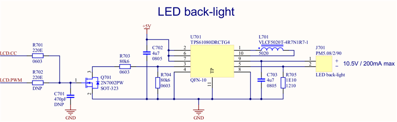
Our backlight has 9 strings of 3 LEDs, 180 mA, we used the datasheet fig. 24 as our reference design, see below.


Our L1 is a TDK VLCF5020T-4R7N1R7-1.


Below a PWM duty cycle of 50% it seems the current goes up again. In fact the 0% duty cycle current through the LEDs equals the current at 100% duty cycle.

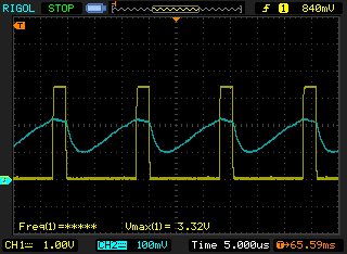
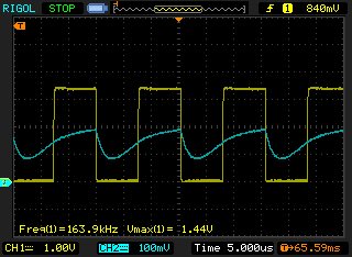
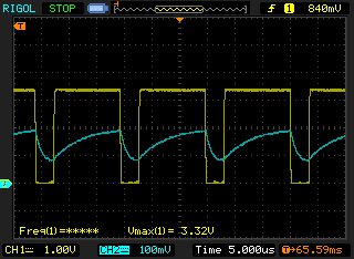
I have included three scope waves on different duty cycles (40, 128 and 200 out of 255).

Yellow is the "PWM Signal" or LCD.CC in our schematics. Blue is the SS signal on the TPS part.

Any insights on why this might happen?


Best regards,


Leon.


  • R1 and R2 set the current through Rset.  When the switch is on, ILED = 5uA*(R1||R2)/Rset.  When the switch is off, ILED=5uA*R1/Rset.  If you want the LED current current to go to zero when the switch is on, replace R2 with a 0 ohm resistor.

  • Jeff,

    thanks. I could not find this simple relationship between SS and the current through Rset, thanks for clarifying.

    Verified this worked by shorting R2.


    Regards,

    Leon.

  • Hello,

    Bringing up this old post from 2011 - sorry, but its related to a problem we are having in a number of ways.

    We have this circuit in our design, its powering a set of LED's in a LCD backlight, in a 7x3 configuration, and we have the current set to 75mA using the same formula mentioned in this post, ILED = 5uA*(R1||R2)/Rset.

    R1 = 10R (this could be 0R as per the above posts)
    R2 = 30.1K
    Rset = 2R

    The problem we have is the noise induced back into the VIN rail. We are using 5V as our input voltage, and we are experiencing up to 500mV of noise, at the exact frequency of the PWM being applied to the FET on this circuit. We have tried adding in many capacitors of varying sizes, even as high as 2200uF (which is not actually feasible for our end product, but it didn't resolve the issue). 2200uF took the amplitude out of the noise significantly, but it did not go away completely, and the noise is still very audible. 2200uF is just not an option for our design though, its way too big. We need another solution. Noise is reduced to 150mV with the 2200uF present.

    We are stuck. We just cannot get this ripple out of the 5V bus which feeds the backlight driver (and other things), and its causing our audio circuit to pick up this noise on the power supply, and you can audibly hear the PWM. This audio is not coming from the actual audio signal, its coming from the power rail somehow.

    Does anyone have any suggestions we can try, to try and prevent the 5V bus from having this PWM noise on it? 

    Our PWM runs at 129Hz, but we have tried from 49Hz to just over 2KHz, and its all present and audible no matter what frequency is present. The tone we get in our amplifier just changes with the PWM frequency used on the backlight.

    We have a 3.3V regulator in the system, being fed off this same 5V rail, and that manages to cut the noise out - which is great. The only thing I can see at the moment is to put another regulator to power our audio, and instead of feeding it with 5V, feed it with 4V or something (have to look if that is even an option), try to isolate the supply that way. But this really is not ideal, as we likely do not have the room on the board. Is there another solution?

    We are actually using the TI TPA6205A1 Amplfier in this case.

    Can anyone help?

    Many thanks in Advance