This thread has been locked.

If you have a related question, please click the "Ask a related question" button in the top right corner. The newly created question will be automatically linked to this question.

TPS272C45: (P)TPS272C45_quiescentCurrent

Part Number: TPS272C45
Other Parts Discussed in Thread: TPS27SA08,

Hi,

I had some time for further testing the samples of the PTPS272C45ARHFR.

I didn´t find an information about quiescent current for single supply, both channels disabled and diagnostics also disabled in the datasheet.

The single switch TPS27SA08 has no current consumption at all in this state (only a few µA).

The PTPS272C45 instead shows a different behaviour. The current consumption is about 2.6mA (VS=24V), altough channels, Vdd and diagnostics are switched off.

If all connections are cut off, except VS and the connection to the load, there is still a current consumption of 0.5mA.

Is this only a problem with the preview-variant PTPS272C45ARHFR or is this normal behaviour?

With kind regards

Marc Nestler

  • Hi Marc,

    The data you see for TPS272C45 should be final.

    The reason TPS27SA08 has much lower current is the standby mode it has. It will automatically enter the standby mode to save power (by disabling the functionality inside the IC). If you look at the Iq for TPS27SA08 during normal mode, it's comparable to TPS272C45.

    Unfortunately, TPS272C45 doesn't have the standby mode.

    May I know is this due to the power consumption requirements in the application that the Iq for TPS272C45 is a concern?

    Regards,

    Yichi

  • Hi Yichi,

    yes, the power consumption of the application is a major problem.

    The low voltage rail of the application is switched off to save energy, but the 24V-system is always present, so the circuits on that rail should have a low power consumption. I thought about cutting of gnd-network and SNS-pin with transistors in low-power-mode, so the only pins left are VS and out2. Then the current flown into the device is descending to 0.5mA.

    Regards

    Marc

  • Hi Marc,

    Yes disabling those would help in power consumption. Please let us know anything else we can help with.

    Regards,

    Yichi

  • Hi Yichi,

    the PTPS272C45 shows another strange behaviour.

    The FLT-pin is always at level device-gnd (if i use the gnd-network (D||R) i have about UF=0.3V, if connected to system-gnd i have 0V). There is no load, the device is at room temperature and the battery voltage is at 24V.

    I can see this behaviour regardless of voltage level at DIAG_EN and SEL and the outputs can be switched on without problems.

    If there is a load connected to one output, the current on the SNS-pin is only 20% of the expected value (external measured load current is 0.5A, internal measured current is 100µA at SNS-pin, so internal measured load current should be 0.12A). It seems that the current at SNS-pin is changing proportional to the external measured load current, but the ratio differs.

    Is this behaviour a known issue for PTPS272C45ARHFR?

    Regards

    Marc

  • Hi Marc,

    For FAULT question, if it has no load connected (open load), then it will trigger the open-load detection and the FAULT will go low and it's the expected behavior.

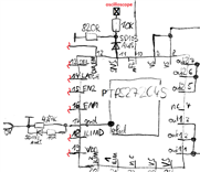
    For the sense pin question, could you attach the schematics for the current sense? We have not seen this issue before.

    Regards,

    Yichi

  • Hi Yichi,

    even if I connect a load (for example 47R with VBatt=24V) and I enable the switch (so there should be no openLoad-fault) the FLT-pin stays at low level. Furthermore I disconnected DIA_EN and the FLT-pin stays at low level. But I checked my test circuit, I did not short DIA_EN with gnd, I only disconnected it (that works with TPS27SA08 but maybe not with TPS272C45). I will check that tomorrow.

    But between load and PTPS272C45 there is a TI LM74801 with an N-ch. MOSFET as ideal diode. Maybe that disturbes the PTPS272C45. Tomorrow I will disconnect this also and will directly connect a load.

    schematics for SNS-pin:

    Regards

    Marc

  • Hi Marc,

    Just to double check, the SNS pin connected with 820R is the GND correct? Also do you have external pull up for FLT pin?

    For the ideal diode, is it in ON state during all time?

    Regards,

    Yichi

  • Hi Yichi.

    Yes, I have an external pullup for the nFLT-pin to 3.3V. I wondered why I could activate the outputs in error state, so I checked the wiring on the test board (I didn´t built it myself), the pullup was accidentially connected with gnd and not with 3.3V. That was the problem.

    The LM74801 is used as idealDiode / 2nd-switch in common drain technology. There is a jumper on my test board to enable/disable it.

    820R goes to system-gnd (not pin17 of TPS272C45) as mentioned in the datasheet p. 29. But as I checked the wiring, I saw that the external wiring of SNS-pin was wrong (my fault). Now the current out of the SNS-pin is correct. 

    Everything works as it should, thank you for your help. Sorry for the mess, I have overseen the wrong wiring on my board.

    Regards

    Marc

  • Hi Marc,

    Glad you have everything fixed. Please let us know if any additional questions come up.

    Regards,

    Yichi