This thread has been locked.

If you have a related question, please click the "Ask a related question" button in the top right corner. The newly created question will be automatically linked to this question.

BQ76952: Question about bq76952

Part Number: BQ76952

Hello:

We now have a project that wants to use your bq76952. When it works, it does not cooperate with the single chip microcomputer, that is, it is protected independently. First of all, please help confirm that bq76952 can work independently without external processor?

In this project, we will use the charge discharge port, that is, the parallel paths mentioned in your document: slua952. Then we need to use the blocking function at the charging port, that is Blocking Leakage Currents in Parallel Paths. We can just use the scheme in this paper, but as explained above, there is no processor in our system. The question is: if bq76952 does not work with MCU, that is, when it works independently, can this "blocking" function be used? If you can, please help explain its working principle?

  • Hello Jimmy,

    Yes, the BQ76952 can work independently. You can configure all your settings and then OTP it to ensure that your settings are the default settings, otherwise the device resets to the factory settings every time it is waken or reset. A guide to OTP the BQ76952 can be found in the  BQ769x2 Calibration and OTP Programming Guide.

    You do not require an MCU to use the circuits for Blocking Leakage Currents shown in the Parallel Paths application report. Section 4 — Blocking Leakage Currents in Parallel Paths of this report describes many circuits in detail. If there is any particular question in particular you can let us know.

    In principle, BMS usually have a single charge and discharge path, when using parallel paths, customers who usually want to separate the lines and may not want any discharge current to go to the charge path (when discharging), or charge current to go through the discharge paths (when charging). So these additional circuits may be needed to block any leakage current from going into the unintended paths.

    I hope this helped!

    Best Regards,

    Luis Hernandez Salomon

  • Hello Luis:

    OK, so if I need this "Blocking Leakage" function, please help me to confige the settings. Which register (or registers) and bit ( or bits ) I need to write?

  • Hello Jimmy,

    This is not a configuration setting, blocking leakage current is done with additional circuitry, which are shown in the application report for Parallel Paths with the BQ769x2

    You can configure the BQ76952 for parallel support by clearing the Settings:FET:FET Options[SFET] bit. This is explained in Section 5.2.3.1 — FET Configuration of the Technical Reference Manual.

    Best Regards,

    Luis Hernandez Salomon

  • Hello Luis: 

      I understand, but I think there's mistake:

    1. First of all, there's no MCU in the whole system.
    2. The bq769x2 working in parallel mode, and for the charge port, we add a blocking circuit.

        And in thus condition, how bq769x2 control the charge mosfet. Because as I understand:

    1. If the charge mosfet keepping on, then the blocking circuit will always on, and no blocking function.
    2. Does bq769x2 will turn off the chage mosfet, and turn on them only after charger connected?
    3. Or a MCU needed to control the charge mosfet, and the blocking function will not working in a MCU-less system?
  • Hello Jimmy,

    An MCU is not required for the BQ76952 to function. As long as the settings are OTP programmed, an MCU is not needed.

    None of the circuits shown in Section 4 — Blocking Leakage Currents in Parallel Paths of the Parallel Paths application report, require an MCU to function. The application report also describes how each function. 

    The purpose of these circuits is to either, disallow discharge current to go into the charge path, or to disallow charge current to go into the discharge path.

    Usually both FETs will be ON (except during a fault), so these blocking circuits may be desired to avoid undesired leakage currents through the wrong paths. The main difference in the parallel configuration, is that the body-diode protection is disabled. You can see comparisons between series and parallel configurations in the Parallel Paths with the BQ769x2.

    Best Regards,

    Luis Hernandez Salomon

  • Hello Luis: 

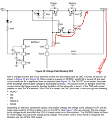
    For the circuit below, as I understand, the blocking function will loss if the CHG was ON, because Q2 will turn ON when CHG was ON?


        So which means if I want the blocking function, I have to shutdown the CHG when there's no charger connected?

        But how to shutdown the CHG when there's no charger connected? And turn on CHG when a charger connected?

  • Hello Jimmy,

    If CHG is ON, Q1 will be ON, Q3 will turn on which turns Q2 ON. I understand now, you are correct if you are using this circuit.

    I apologize for my confusion. Yes, the CHG pin would need to be OFF to block the leakage current there. You probably will have to manually control the FETs using commands. Since some protection recoveries are made difficult with the parallel configuration. As an example/consideration, you may have to implement a way to detect SCD on the charge path (in case of charger short) to turn-off the CHG FET, as the DSG FET is now in a different path (and this FET is usually the one used to protect in the case of a SCD.

    See Table 5-8. FET Control Subcommands of the Technical Reference Manual for a list of the commands that can be used to control the FETs, also read Section 5.2.2 High-Side NFET Drivers. This older e2e thread discussed how to use the commands, which may be helpful: https://e2e.ti.com/support/power-management-group/power-management/f/power-management-forum/1051647/bq76942-write-fet_control-under-i2c 

    The current path you illustrated may add a load to the charge pump of the IC, which may increase the supply current when the CHG FET is high. RGS2 must be large to minimize the load on the charge pump, if the load is too high, the charge-pump may be discharged and the FETs may turn-off.

    Best Regards,

    Luis Hernandez Salomon