This thread has been locked.

If you have a related question, please click the "Ask a related question" button in the top right corner. The newly created question will be automatically linked to this question.

UCC28070: Input voltage dip

Part Number: UCC28070
Other Parts Discussed in Thread: UCC28019

Hi,

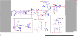
  I am using ucc28070 for IPFC of 2.2kw. My output is set to 380.  Problem is once pfc starts(after reaching vsense÷0.7), input voltage is falling, also duty cycle is going to 96% always all the time and heating g in the device.kindly support

  • Also variable makes huge sound as it not support 

  • Hello Skanda,

    Thank you for your interest in the UCC28070 PFC controller. 

    From your description of the input voltage falling, constant 96% duty-cycle, and the Variac making a loud noise, I suspect that the power switches are commanded to be on too much and the high input current is overloading the Variac.  However, the impedance of the Variac is limiting the current enough so that any protection device (fuse, circuit breaker, etc) is not operating. 

    Constant high duty-cycle implies that there is some break in the control feedback loop.  VSENSE may be improperly clamped below regulation, or maybe the phase current-sense is not functioning properly. 

    Is it possible for you to provide a schematic diagram of your PFC design for review?  Also, please examine your pcb to verify that all polarized components (diodes, capacitors, CS-transformers, etc.) are placed in the correct polarity.  And check for unwanted short-circuits between pads and networks from stray solder-balls or wire whiskers. Even if the schematic is correct, the board may have an assembly error.

    Regards,
    Ulrich

  • Sir,

       I tried to use the same circuit in a single stage configuration(Only one MOSFET at a time)  PFC using UCC28019. It was working fine without any issue.  When I tried to use interleave action using UCC280070, then only this issue comes.

  • Hello Skanda,

    Thank you for providing the power stage schematic diagram.  It is small and a bit fuzzy (not easy to read) but I wonder if there is an issue with the current sense transformers.  I could see the polarity marks on the CT windings, so I tried to look up their datasheet.  If I read it correctly, T1 and T2 part numbers are CS4200, is that correct?  Coilcraft makes a CT with part number CS4200V-01L with 1:200 turns ratio.  Is that correct?

    From their data sheet, the 1-turn primary winding connects from pin 2 to pin 3, with polarity dot on pin 2.  Then the 200-turn secondary is from pin 1 to pin 4 with dot on pin1.  Your schematic shows the primary from pin 1 to pin2.   If you are using a Coilcraft CS4200V-01L and if the board is connected as the schematic shows, then it implies that you have a 200-turn winding (pin1-to-pin4) from the boost inductors to ICSA- and ICSB- (effectively primary-GND).

    Basically, this would be a direct path from the rectified-line positive back to negative, with several inductive and low-resistance impedances in series. Please check this possible situation. 

    Regards,
    Ulrich

  • Sorry. Ignore previous mail. 

      1 turn side is connected between inductor and Moffet. 200 turns side is connected in controller side.polarities are checked in single stage pfc configuration. All are fine. Then only I connected to interleaved pfc configuration to ucc280070.

  • Hello Skanda,

    Since operation works in a single-phase arrangement with UCC28019 as controller, and does not work in a 2-phase arrangement with UCC28070 as controller, there must be some problem with the way that the 2-phase control is connected.  The previous power-stage schematic does not show connections to the UCC28070 controller.  There are more than one PFC GND nets and the CT burden resistors are returned to a net name different from the other GNDs.

    There is not enough information on that schematic alone to aid in debugging this issue. 
    Can you please provide a complete schematic of the entire PFC block, preferably in a PDF file.  The small screen-capture picture does not have enough resolution to read the text properly.

    Regards,

    Ulrich       

  • Hi,

       I don't want to share exact schematic in community as it is against company norms.lt will be better if you allow me through mail. Kindly share your email detail for further discussion.

    My ID:skandarama.k@skanray.com.

    I have connected to a ic in pcb which is used by another variant for pfc, where that board worked fine. Here for testing purposes I connected through wires for feedbacks and gate signals.ground plate is not there for board. Current feedbacks are taken differently and CT burden is given near to the controller pin.

  • Also vcc of IC is is given to 12V. Is it enough?

  • Hello Skanda,

    I'll reply to your email and you can share the schematic privately.

    The highest UVLO level of VCC on UCC28070 is about 9.6V, so as long as the 12V source for VCC does not dip below that threshold, the VCC will not have any effect on the PWM control.

    Regards,
    Ulrich