This thread has been locked.

If you have a related question, please click the "Ask a related question" button in the top right corner. The newly created question will be automatically linked to this question.

TPS1H100EVM: Working Principle clarification

Part Number: TPS1H100EVM
Other Parts Discussed in Thread: TPS1H100-Q1

Hello,

I was evaluating TPS1H100-Q1 MOSFET for my design with evaluation module. 

For my requirement, I need Internal current limit to be set at 900mA. MOSFET should be used as current limit element connected in series on supply line.

with the calculations provided in user guide, I set the value of R7 pot in evaluation module to  2.740K.

with this when I measured the results I observed that,

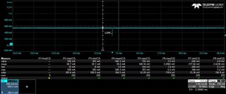
When I linearly decrease the load resistance, the current goes till ~1000mA limit then reduces to 900 mA. (I do not understand this behavior why it is increased by 100mA above the set limit? Is there any hysteresis?)

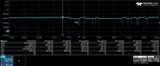
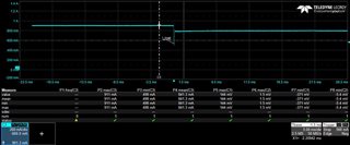
if I further reduce the load, it tries to keep the load current to 900mA limit till overload current reaches ~1350mA (1.5 times of set current limit, as specified in datasheet also).after that load current drops to value of  ~200mA reducing the output voltage further.

Please let me know if the clarification for the above query marked in red and the solution for the same.

Let me know if you need any additional info.

  • Hi Vivek,

    The higher current limit value might due to the current creep behavior for current limiting events. The current limit is higher when the load current increased slowly as the FET is in its linear region longer. Please refer to section 4.1 in this app note for more info.

    www.ti.com/.../slva859b.pdf

    Please let me know if you have additional questions.

    Regards,

    Yichi

  • Hello Yichi,

    Thanks for your response.

    We tested TPS1H200Q1 in hold mode for three current limits , 500mA , 600mA and 800mA . 

    We linearly increased the load in each case to cross the current limit and checked the practical output on oscilloscope. Attached waveforms for you reference.

    The observations is as follows:

    * for 500mA the limit is around ~542mA => error 42mA

    * for 600mA the limit is around ~648mA => error 48mA

    * for 800mA the limit is around ~901mA => error 101mA

    If we consider the accuracy values in table 4  in the application note shared by you, there is enough margin for upper limit error, for example, for 800mA the upper limit is 920mA , for 600mA it is 690mA  we see lot of variance above.

    Please correct if our approach for calculating upper bounds are correct ? if yes let us know if there is a way to calculate this error more accurately ?

    Regards

    Vivek

  • Hi Vivek,

    The current limit bound calculation is correct. There's one more factor which is resistor error - as resistors will have their own error in their value too. If you want more precise calculation, you can take into account the percentage error in the resistor you used for current limiting. Then it will have a more accurate results for the upper bounds. The approach is correct in this case.

    Please let me know anything else I can help with.

    Regards,

    Yichi