Other Parts Discussed in Thread: LM5146
I am working on a project using the LM5141 as the controller which feeds HO/HOL and LO/LOL to two gate drivers that drive two mosfets each. At first I was thinking that I need both gate drivers for isolation but after looking at the design further, I think I can remove the second gate driver and have the two bottom mosfets driven directly by the LM5141 but keep the first gate driver to drive the top two mosfets. I have tried modeling this in Cadence but I am having lots of ringing on HO/HOL.
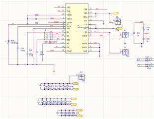
Below is the schematic of the original design that has been working fine. I would like to remove U6 and drive Q3 and Q4 from signal A and B from U9, respectively.


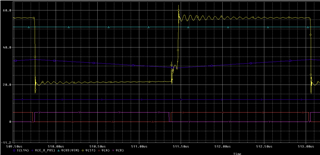
The output of signals A and B on the working model with two gate drivers look clean with no ringing as seen below
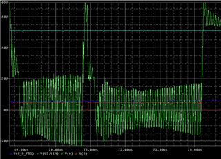
But when I try to drive Q3 and Q4 directly from the LM5141 I get alot of ringing in signal A. Can anyone offer suggestions?