This thread has been locked.

If you have a related question, please click the "Ask a related question" button in the top right corner. The newly created question will be automatically linked to this question.

LM73100EVM: schematic check

Part Number: LM73100EVM
Other Parts Discussed in Thread: TVS2200

Hi

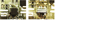
The customer factory found that the LM73100 burned out:

Fail rate: 3/90

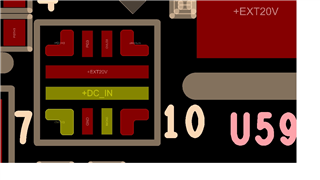
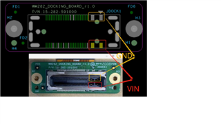
The phenomenon of burning is: U59 PIN6 PIN7 PIN9 is short to GND, and the pad has been burned.

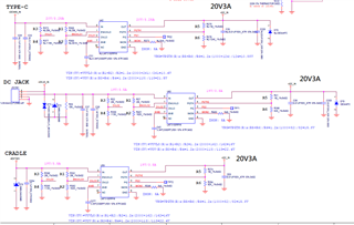
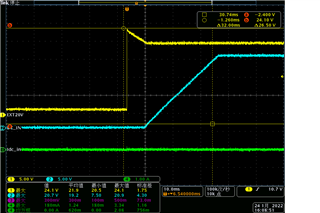
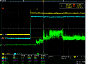
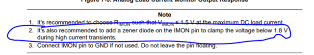
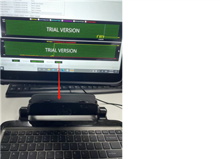
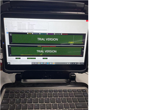
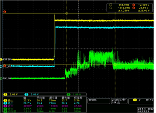
There are measured Input, Output voltage, and current waveforms such as accessories, all within the SPEC range, Is there a problem with the design schematic?

  • Hi Gareth,

    Thanks for reaching out. I will get back by tomorrow.

    Regards

    Kunal Goel

  • Hi Gareth,

    Please help with below questions:

    1. What were the test done on board? At what test did device fail? Did it fail at first power up?

    2. what is ambient temp?

    3. only pin 6,7,9 are damaged? other pins look fine?

    4. only U59 is getting damaged? any other component getting damaged?

    5. Some recommendation on design:

    5.1 Please share TVS datasheet. It does not look good selection.

    5.2 

    6. Did customer do short circuit test?

    7. What is the load at output and what is load normal and max value?

    Regards

    Kunal Goel

  • Hi Kunal

    1. The tablet is matched with the charging base, first plug the 20V adatper on the base, and then plug the tablet into the charging base, so repeated tests will cause burns.

    2. The ambient temperature is around 22C, and testing with a bare board will also occur.

    3. Yes, only PIN 6 7 9 is broken, other PINs are OK.

    4. Only the U59 is damaged. The lighter one is that the Pad on the PCB is not burned out, but the U59 is damaged. It is OK to replace the 73100. The worst is that the PCB Pad is burned out, and it is impossible to replace the 73100.

    5.1 as attachment(SMBJ24A)

    Littelfuse_TVS_Diode_SMBJ_Datasheet.pdf-1108540.pdf

    5.2 IMON PIN not reserve TVS.

    6. NO

    7. The output is to supply power to the tablet, the Normal value is about 1A, and the maximum is about 3.2A. As shown below:

  • Hi Gareth,

    1. So tablet is inserted into a charging base? U59 is in tablet or in the charging base?

    2. So customer factory is inserting tablet into charging base multiple times?

    Regards

    Kunal Goel

  • Hi Kunal

    Customer response is as follows

    1.So tablet is inserted into a charging base? U59 is in tablet or in the charging base?

    ->yes, U59 is in tablet.

    2. So factory is inserting tablet into charging base multiple times?

    ->yes, it doesn't take many times, it will burn after plugging in a few times, and the laboratory can also simulate burning.

    Thank you

  • Hi Gareth,

    Thanks for replying. 

    1. the 3 units that have failed were they inside tablet when failed (I mean complete product) or a pcb was inserted in charging base?

    2. Units fail just at the time when plugged into charging bases or they fail after some further hardware or software testing? 

    3. What do you mean by laboratory could simulate burning?

    4. One more thing I want to point out , can customer check when they insert into cradle if VIN supply is coming before GND connection. if we supply voltage to VIN pin but GND is floating that can cause damage.

    Regards

    Kunal Goel

  • Hi Kunal

    1.complete product(Assembled flat panel machine)

    2.Only plugged into charging bases.

    3.It can be reproduced by plugging and unplugging a few times in the factory, and it can also be reproduced in the laboratory. 

    4.CONN are all fool-proof, and they are all inserted vertically, so there should be no such problem, as shown in the following figure:

  • Hi Gareth,

    Generally during hot-plug , failures happen due to transient exceeding device abs max pin rating. So I would propose these recommendations:

    1. SMBJ24A is not a right choice. Its breakdown voltage is above recommended max VIN of 23V. Its clamping voltage is around 39 which is very high, it should be below 28V. A TVS like TVS2200 would be a good choice. 

    2. Also selecting output schottky diode with lower VF like B330A. https://www.diodes.com/assets/Datasheets/ds30891.pdf

    3. Adding some more cap at input and output.

    Regards

    Kunal Goel

  • Hi Gareth,

    Let me know if you have any further concern.

    Regards

    Kunal Goel

  • Hi Kunal

    Thank you for your support

    Customer will replace your suggested TVS specs first

    Thank you