This thread has been locked.

If you have a related question, please click the "Ask a related question" button in the top right corner. The newly created question will be automatically linked to this question.

TLV743P: TLV743P PSRR measurement tips and condition

Part Number: TLV743P

Hi, I was trying to measure the PSRR of TLV743P with below configuration 

1. Cin = Cout = 0402/X5R/1uF/6.3V capacitor 

2. Vin = 2.3V, Vout = 1.8V, I-load = 300mA 

May i know if this is the correct operating condition for the PSRR measurement shows in the datasheet 

If it's not, can you help to let me know what is the proper condition to use to get the correct PSRR result from the experiment? 

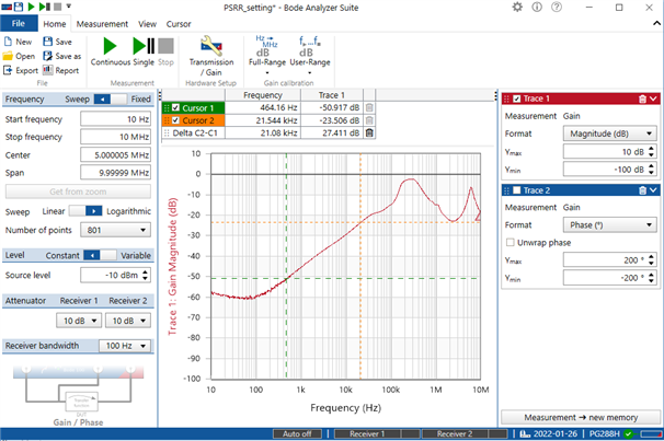
The result i got from bode 100 shows below: 

the result is lower than datasheet about 

5-10 db @ 100Hz

5 db @ 10kHz

100kHz is similiar with the plot but the not match with the EC table 

I was trying to get the same result compare with fhe datasheet 

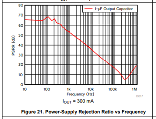
The EC table show that: 

The table seems to be typo for the 100kHz result? which should be about 18dB? 

Here is the capture of my bode setting for the measurement, i would also like to know if there are issues with my bode 100 configuration if you have suggestions 

Can you help to let me know if there are difference between the operating condition compare with datasheet from the previous description? 

Please let me know if there are suggestions from your side, thanks a lot. 

  • Hello Gary,

                     Unless required for stability, please remove CIN when making PSRR measurements. At higher frequencies it provides a path to GND, attenuating the input signal before it reaches the LDO, and thereby making the PSRR measurement better than it actually is. I do not see any functional/setting mistakes, please try the experiment without CIN. Although there is nothing wrong in interpreting PSRR as a negative value, to get positive values (like in our datasheet, Figure 21) swap the Bode 100 inputs (Input 1 connected to OUT and input 2 connected to IN). Thanks!

    Regards,

    Srikanth   

  • Hi Srikanth, 

    Thanks for your reply, but it seems that i can plot the same result showing in the datasheet even with Cin is on the board. 

    The PSRR will be worse if there are no Cin, so it may still not match even take the Cin off from the board, so i was wondering to know what is the setup to get similiar result with the datasheet? 

    can you help to tell me the componenet usage of the setup for measuring at the datasheet? 

    And is there typo for the datasheet? it seems that PSRR show in the table not match the curve. 

    Thanks a lot. 

  • Hello Gary,

                      Yes, I agree that the 100KHz entry in the table does not match with the curve. It is quite likely a typo. I do not see too much wrong in the PSRR plot you have generated. It is not atypical to see ~3-4B of variation in PSRR from device to device. The level of 'cleanliness' (lesser parasitic's the better) of the measurement setup will also result in ~3-4 dB variation. Below is a description of our typical setup.

                       The EVM recommended for this device (https://www.ti.com/tool/MULTIPKGLDOEVM-823), the Bode 100 and a line injector (we use Picotest J2120A) or a summing power Amp (to add the AC & DC signals) is typically the setup we use to make PSRR measurements. The EVM will help you select the components. After the setup is ready could you incorporate the following:

    (a) Uninstall the input Cap

    (b) Change the Source Level (AC signal Input) setting from 'dBm' to 'VPP'. This change can be made in the settings (Ctrl + Shift + O). We typically inject an AC signal with 50mV - 100mV peak to peak magnitude. 

    (c) With the Bode 100 inputs, connect CH1 to OUT and CH2 to IN. As I mentioned earlier, this is not very significant, but this way you will get positive PSRR values.

    Implementing this setup and recommendations will help you mimic our PSRR setup. and that will help us make a like-for-like comparison. 

    Thanks!

    Regards,

    Srikanth