This thread has been locked.

If you have a related question, please click the "Ask a related question" button in the top right corner. The newly created question will be automatically linked to this question.

UCC28730: Instable Switching

Part Number: UCC28730
Other Parts Discussed in Thread: UCC24650, UCC28740, UCC28742

Hi,

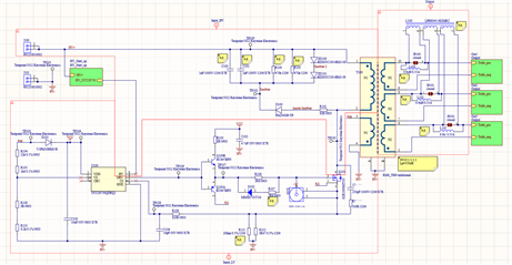
I have designed a 10 W Flyback-Converter with 3 Outputs with a Inputvoltage of 60-1000V and an Outputvoltage of 15V.
I am now trying to put the PCB in operation, but I am facing unstable switching behaviours. To simplify the the process I have started with only on connected output winding. I am using a 10 to 1 winding ratio and a clamp with two 100V Zener-Diodes. I have also added a snubber from the  primary switch drain to primary side GND to reduce the ringing on AUX/VS during the demagnetisation phase.

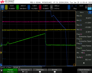
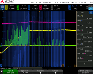
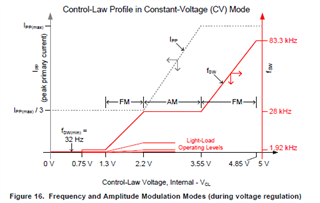
I have obsered that even with strongly dampened ringing on the Aux Pin (blue) the switching behaviour would be instable. The controller seems to regulate the output at first, but then switches to higher frequencies before it switches of. In some configurations the switching frequencies would go to over 100kHz, which lets me assume that the controller is going back into its high-frequency start-up state. Are you familiar with this behaviour? Is there a maximum dV/dt that the slope of the AUX/VS should have during demagnetisation? The slope at VS-pin is very close to 0.125V/200ns. Tdemag min is achieved at Ippmin to Ippmax.

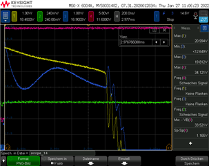
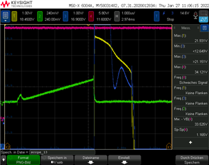
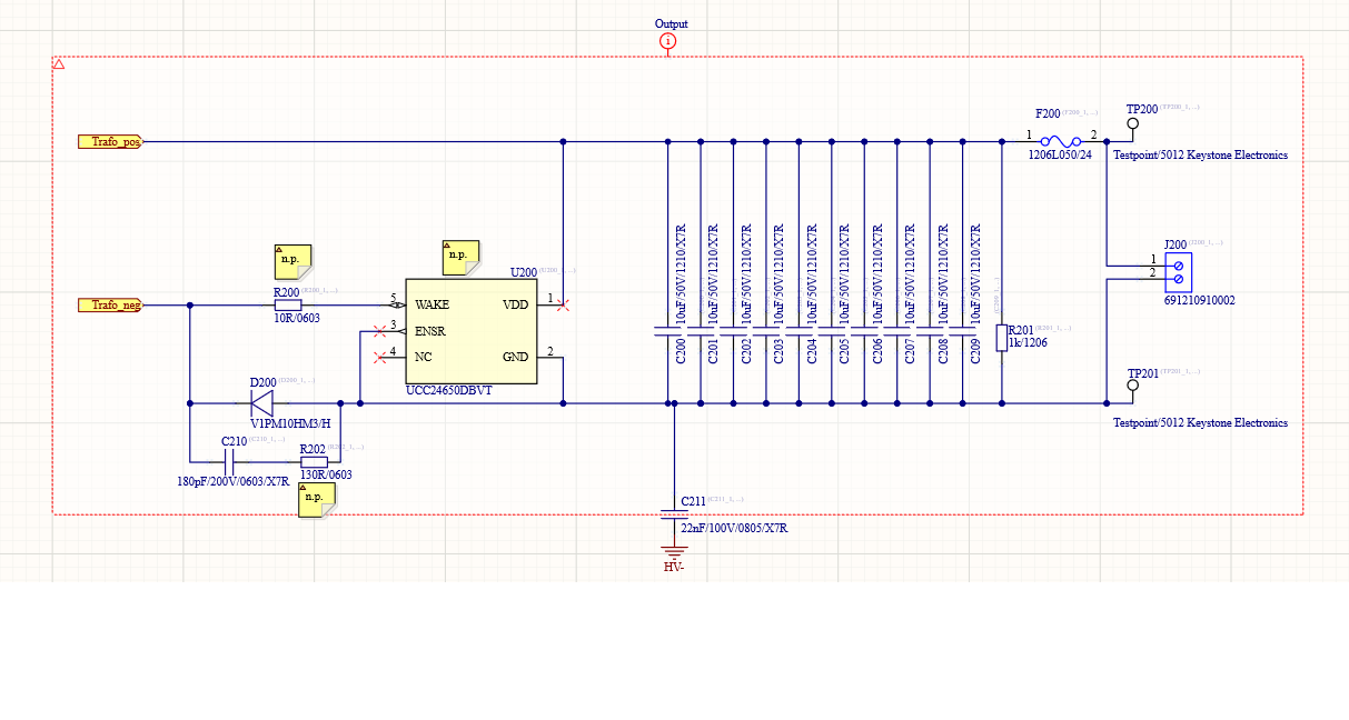
I also observed a spike at the end of the demagnetisation phase on the Vaux (blue). An opposing spike can be observed on the secondary winding voltage (yellow). (These pictures where taken with different value for the snubber). Could this influence the voltage sensing and regulation? I have already tried using shottky-diodes as rectifiers and various snubbers for the rectifiers. I did not seem to influence the spikes.

Kind regards
Ludwig Jostes

  • Hello,

    I am evaluating the issue and will get back to you soon.

    Regards,

  • Hello,

    Sorry you are having issues with your design.   

    Do you have a schematic that you can share for review?

    You can use the Excel Design calculator or Webench to check your design.  Both can be find in the UCC28730 product folder under design tools.

    https://www.ti.com/product/UCC28730?keyMatch=UCC28730&tisearch=search-everything&usecase=GPN#design-development

    The following link will bring you to an application note that describes primary fault sensing most common issues and how to resolve them.  The UCC28730 has primary fault sensing and you may find this application note helpful.

    https://www.ti.com/lit/pdf/sluaac5

    Regards,

  • Hi,
    could I send you the schematics privately?
    Kind regards

  • Hello,

    The e2e is on line support.  So if you can send it I will not be able to review it.  However, you can compare it to the UCC28730 evaluation module schematic to see if there is anything different from your design compared to the evaluation module.

    https://www.ti.com/tool/UCC28730EVM-552

    I also believe the Webench design tool and application note SLUAAC5 should be helpful as well.

    Regards,

    Mike

  • Hi,
    here are my schematics.
    /resized-image/__size/1213x648/__key/communityserver-discussions-components-files/196/2728.Output_5F00_Schematic.png

    /resized-image/__size/1493x240/__key/communityserver-discussions-components-files/196/2538.Main_5F00_Schematic.png

    As stated before I have already tried various snubber configurations following sluaac5. I have also tried the advice in SLUA783.Please let me know, if you find an issue with the design or have any other advice.
    The components with the note "n.p." are not soldered to the board. When trying one output the according jumper  (JP101, JP102 or JP103) was shorted/closed, the others were left open and the rectifier diodes of the other outputs were disassembled.
    Regards

  • Hello,

    In your schematic you have what appears to be inductors and a coupled inductor across the output rectifier.  Not sure what these are for and I would try removing them.  This may also interfere with the UCC24650.

    Also you need a pre-load resistor on the output to keep the design in regulation under no load conditions. Your schematic does not show one and it is needed. Generally 1 to 2 mA of load current will do it.  I believe the UCC28730 data sheet gives recommendations on how to set this pre-load resistor

    I reviewed the thread and noticed your input range is quite high at 60 V to 1000 V.  Generally in PSR flyback design the input is limited to roughly 9 to 1.  So this design may not be possible.  The following application note describes how to design a flyback converter with a wide input range that uses primary side regulated control similar to the UCC28730. https://www.ti.com/lit/pdf/slua781  That being said I would consider changing your input range to 9 to 1 if possible and following application note slua781.

    In regards to your primary to secondary turns ratio.  This is generally done on volt seconds with a duty cycle cycle or roughly 0.55.  You can estimate with 50%.  Np/Ns =  60V/15V = 4.  So your turns ratio is not correct for a minimum input voltage of 60 V.  I would consider changing this as well.  Please note that your primary magnetizing inductance needs to support the designs output energy.

    Since your input range is so wide you may to design two converters. If you can not adjust the range to less than 9 to 1.  One to work from 1000V to 120 V input and one to work work from 120 V down to 60V.   It is easier to design with 5 to 1 input ranges.  You might consider one range to 1000V to 200V and the second to be 200V to 60V.   You could even go 1000V to 500V and 500V to 60V.

    Regards,

  • Hi,
    the inductors were planned to improve crossregulation in case that would be needed. They are marked with n.p. and are not populated as well as short circuited by the jumpers (JP101, JP102 or JP103 respectivly) as stated.

    You can see the preload resistor on the other schematic, which is the output sub schematic. It even sets 15mA preload.

    A change of the input voltage range is not possible. Also one of the most important design targets is a small size and weight. an aditional converter is therefore not an option.

    A Nps=4 is not possible since the UCC24650 is used on the secondary side for fast load transient response. It can only handle 200V. The primary inductance is supporting the ouput power. I have had the transformer running with all secondary windings paralleled to one output on the Evaluation Board at 10 W, however also not really stable.

    Do you have an idea what could cause the peak at the end of tdm? Does it have something to do with the sampling of the VS-Pin? Can you find any other problem with the Aux signal, that could cause the instability?

    I am thinking of using the UCC28740 instead to improve stability of the regulation. This would however require a optocoupler feedback network, which I was trying to avoid.
    Regards,

  • Hello,

    The inductors/couple inductors may be causing some of your instability.

    Sorry about missing the pre load inductor.

    The UCC28730 will not work with the incorrect turns ratio.  That may also be causing your instability.

    If your turns ratio is incorrect.  The KCC ratio of ton/(ton+toff) cannot be met and it will also cause an instability.  KCC is met at the designs maximum frequency and s the frequency decreases the ton/ton+toff ratio does not have to meet KCC.

    Recommendation.  Try correcting the turns ratio and disconnecting the UCC24650 wakeup chip.  To see if you can the design to work.

    If you need a fast transient response you may consider switching to the UCC28742 with opto feedback.  This will not have the negative voltage limitation of the UCC24650.  It uses a similar control law as the UCC28730 and the power stage should work once debugged.

    https://www.ti.com/product/UCC28742?keyMatch=UCC28742&tisearch=search-everything&usecase=GPN

    Regards,

  • Hi,
    the inductors are not populated/assembled.

    Where is this KCC value stated in the data sheet of the UCC28730?
    I am testing at 100V at the moment, so the on time would even be quite long compared to the minimum ton stated in the datasheet.

    I will try the UCC28740 since it has a HV-Startup Pin and the control law also seems very similar.

    Regards,

  • Hello,

    Not sure why they did not have it in the data sheet.  In all other devices that use similar control law it is listed as KCC and not Dmag.  Dmag of 0.423 and the transformer needs to be set for the turns ratio at minimum input voltage and a Dmax of roughly 1-Dmag.

    Regards,

  • Hi,
    that is the case in my design.
    What could be caused by the high turns ratio is that the tdemag is too short. However, even with my 10:1 ratio tdemag is >tdemag_min=1.2us (according to datasheet) at Ipp/3. Therfore this should not be the problem.

    Regards,

  • Hello,

    If you do not set the turns ratio and primary magnetizing inductance up correctly.  The converter will not control the duty cycle correctly and constant current will not work correctly.  The UCC28730 control the duty cycle with frequency (FM) and peak current (AM) modulation.  

    Dmax occurs at Fmax when designed correctly.  If you do not set the turns ratio and primary magnetizing correctly you will not be able get the correct duty cycle and the control law will nut function correctly.

    Regards,

  • Hi,
    from my understanding, the controller only senses the current and switches off, when the current level according to V_CL is reached. Why would the duty cycle matter to the control loop when it is controlling currrent not duty cycle? (Not considering transformer utilization or  similar)
    The converter is set up in a way that it produces 10W of output at approx. 45kHz at Ipp_max at a duty cylce of approximately 0.42. This resulted from the requirments for t_demag_min. The way I understand the answer to my question here https://e2e.ti.com/support/power-management-group/power-management/f/power-management-forum/1057195/ucc28730-maximum-frequency-of-ucc28730?tisearch=e2e-sitesearch&keymatch=ucc28730# is, that it does not matter if maximum duty cycle is reached before 83kHz, since the controler will only go into constant current mode earlier. Is that correct?
    Therefore the converter would be able to supply event more power (if thermally acceptable), but I don't care about that, since it seemed the only way to meet all requirments. I also don't care about having much higher power in the constant current mode, since it is not needed in my application.
    Regards,

  • Hello,

    If you do not select the transformer turns ratio and primary magnetizing inductance correctly the controller will not work correctly.  You are correct you don't have to design for a maximum frequency of 83 kHz.  You could design for a maximum frequency of 48 kHz.  The transformer turns ratio and Lpm will limit the frequency and duty cycle.

    If you have a turns ratio of 10 at 60V the output will only be able to achieve 60V/10 = 6 V.  To achieve 15 V would require a turns ratio of 4.

    Regards,

    Mike

  • Hi,

    that may be correct for some converters, however not for a flyback converter.
    A higher turns ratio will only mean that the demaggnetisation time will be shorter, since the reflected voltage from the secondary to the primary is n*Vout. Lp can be charged and discharged at various voltages as long as tdemag+ton<1/f.

    Could you please have a college look at this issue as well?

    Regards,

  • Hello,

    The flyback is a transformer and the voltages will be couple through the transformer turns ratio.  If you change your transformer turns ratio and set the magnetizing inductance of the transformer per the data sheet recommendations your instability will go away. 

    There are Webench design tools, application notes and I believe there is an excel design file that you can use to check your design.  This another way to check your design. 

    https://www.ti.com/product/UCC28730?keyMatch=UCC28730&tisearch=search-everything&usecase=GPN#tech-docs

    Regards,

    Mike