This thread has been locked.

If you have a related question, please click the "Ask a related question" button in the top right corner. The newly created question will be automatically linked to this question.

LM3150-500EVAL: LM3150MHX

Part Number: LM3150-500EVAL
Other Parts Discussed in Thread: CSD16342Q5A, LM25145, LM3150, LM25149, LM25148, LM5146, LM5145, LM63460-Q1

Hi TI,

I'm going to use this convertor in my PCB board for below mentioned configuration, 

Vin = 12 V to 20 V

Iout = 6A

Vout = 5 V

Ambient temperature = 90 degree celsius

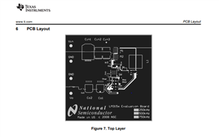
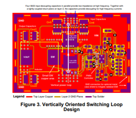
using  CSD16342Q5A FET (webench suggested part) , In Evaluation Board application note AN-1900 (SNVA371) for PCB design there it has PCB layout for placing FET,

my query is if I follow the layout whether it  achieve FCC class B radiation emission testing ?.

  • Hello,

    The LM3150 has an older PCB layout design. Please review the power stage layout techniques as described in app note SNVA803. Also, see the PCB layout guidance in the LM25145 and LM25148 datasheets. The LM5145, LM5146 and LM25149 EVMs are worth looking at just to see the MOSFET and input capacitor placement, as this is critical to minimizing radiated EMI.

    Regards,

    Tim

  • Dear Timothy,

    I have read the app note SNVA803. for abatement of EMI it is clear , actually the board is going to work on ambient temperature of 85 degree celsius whether it will withstand ? please give your comment for heat dissipation (at switching node). if I design like  as it mentioned in app note SNVA803 for LM3150 , what should be Ambient temperature range ?

  • Hello, the general recommendation is keep the SW node copper area as small as possible as that is a radiating node. The heatsinking for the low-side FET is done by the inductor (connected to VOUT plane), whereas the VIN copper area provides heat spreading for the high-side FET.

    The ambient temperature isn't really the main parameter for ICs with power dissipation. It's really the junction temperature as the junction-to-ambient temperature rise is based on the internal power loss. Recommended TJ max for most controllers is 125°C. The LM5146 and numerous automotive grade controllers are rated to 150°C.

    Take a look at the LM5146 and LM25149 EVMs as they were designed based on the techniques used in app note SNVA803. In fact, I recommend using the LM25148 or LM25145 42V controllers here instead of the LM3150. Another option (with a much easier layout) is to use a converter with internal FETs, e.g. the LM63460-Q1 is a recently released 36V/6A converter, and some stock of ICs is currently available in the TI store if needed.

    Regards,

    Tim