This thread has been locked.

If you have a related question, please click the "Ask a related question" button in the top right corner. The newly created question will be automatically linked to this question.

LM5039: LM5039 soft-start circuit

Part Number: LM5039
Other Parts Discussed in Thread: LM5027

Hi Team,

There is a good new that we DIN LM5039

And there have one thing need your support!

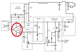
If the secondary side of LM5039 refers to the reference SCH (OPA feedback) of SPEC (p25)
Do we have a soft-start circuit to suggest?! Thanks...

lm5039.pdf

  • Hi 

    I will reply to you later.

  • Hi Jerry

    I wanted to follow up to see if you were able to get any feedback ,THX

  • Hi cheng

    LM5039 have a soft start pin to make the output voltage increase gradually. Do customer want to add another soft start circuit?

    Jerry

  • Hi Jerry

    Yes , customer want to add another soft start circuit!!
    One more question about Application Note 2025 LM5039 Evaluation Board (p7 FIGURE7)


    If we want to eliminate the red box in the picture below!! (Because it will be more obvious if the load is larger (10A) during the test!!)

    Would it be helpful to modify the schematic somewhere? THX

  • Hi Jerry

    First of all, customer still have space to reserve the soft start circuit on the secondary side.
    In addition, the phenomenon of red circle of figure 7 is found!! (The more overload, the more obvious)
    If the red circle issue has a solution ,customer could not need the lay soft start circuit! THX

  • Hi Cheng,

    In my opinion, SS pin voltage is used  to compare with Ramp ignoring the COMP pin in soft start. As you can see in Fig.7. Red circle is only existed a short time interval. And the soft start is still normal after red circle interval. I recommend that you can let customer test pulse width in red circle interval. If pulse width is normal, the red circle issue is not caused by the compensator loop and SS pin. If that, even though you add another soft circuit in compensator loop, it's useless. If pulse width is large in red circle interval, I think we can consider to use another soft start circuit in compensator loop to suppress the voltage spike in red circle interval.

  • Hi Jerry

    Thank you for your feedback!

    One more question, currently client use LM5039, if client want to refer to Secondary Side Soft-Start of LM5027 (attached spec p8~p10 as shown below)

    Does the Secondary Side Soft-Start SCH apply to LM5039? THX

    LM5027.pdf

  • Hi Cheng,

    The key point that you want to start up smoothly is to make the Vref clamp to ground till the ss pin begin to rise. After the ss pin begin to rise, you can release the Vref. I think this circuit can be apply to LM5039. But you need to adjust the parameter of 1000pF cap so that the clamp time will be suitable for your application.

  • Hi Jerry

    In addition to referring to the LM5027 SPEC!! Is there any other information for reference?!
    (It is best to use OPA for feedback!! As the red box below) THX