Hello, my team has been working on integrating the LM5175-Q1 buck-boost into our design. We have an input voltage ranging from 6.5 - 32V, and a 24V output at 12.5 A peak current. We have been attempting to simulate this circuit using PSpice for TI but the circuit does not behave as expected. Both the QuickStart tool and Webench were used for the component values and schematic. The Webench simulation works as expected, however we need to integrate this into our PSpice design. Suitable FETs were selected to match the rated current and voltages called for in Webench.
For the simulation to run without convergence errors, several parasitic resistances were experimentally placed into the circuit, labeled as “RparXX”. No matter the input voltage, the output tends to stay right around 0V. LDRV1 shows a duty cycle near 100%, HDRV1 and LDRV2 sit at 0V, and HDRV2 sits at 7.5V.
Do you have any ideas what may be causing this issue? Also, is the model for this chip fully compatible with the latest version of PSpice for TI? We have exhausted all possible solutions and tried many component values and modes of operation. Each yields the same results.
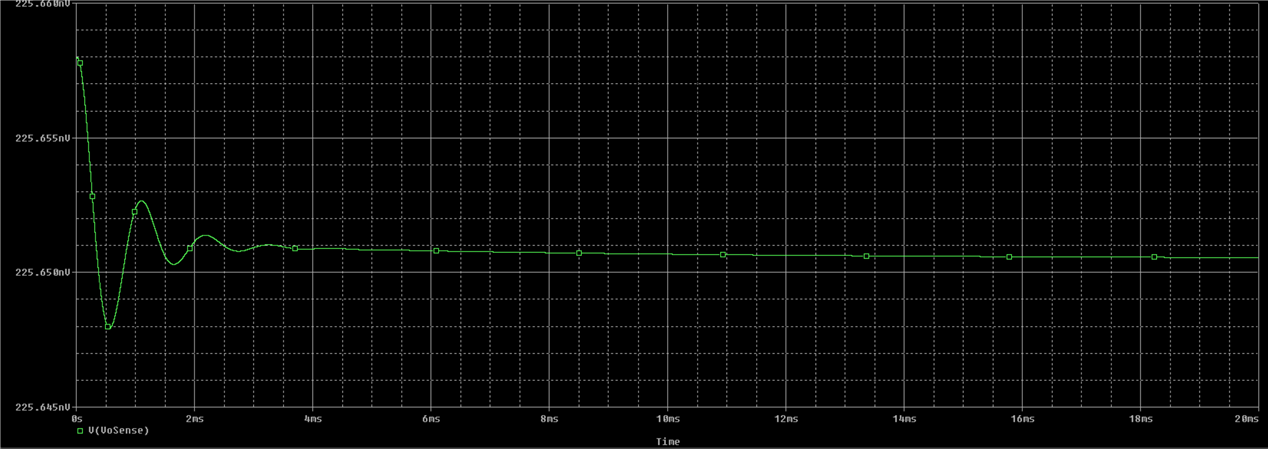
I will attach the simulation files, schematic, and plots of the output (green) at Vin of 10 and 30V (red).
I appreciate any support you can offer with this.
Thank you,
Aidan Carrigan