This thread has been locked.

If you have a related question, please click the "Ask a related question" button in the top right corner. The newly created question will be automatically linked to this question.

LM61495-Q1: How to connect the grounds

Part Number: LM61495-Q1

HI ALL,

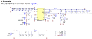
I design a PCB card with LM61495QRPHRQ1 component.

The component has 3 grounds and 2 input voltages:

- AGND, PGND1, PGND2

- VIN1, VIN2

What is the correct way to connect the grounds on PCB and electrical drawing?

1. With a short resistor between AGND and PGND1 + short resistor between AGND and PGND2

2. Not use with a short resistor between grounds. connect PGND on external layer with plane and AGND connect to internal ground layer with via.

I would appreciate your help.

Thanks.

  • Hi,

    AGND and PGND1/2 should be connected together through a single point node. 

    Refer to the EVM User's Guide for layout and example of how this is done. 

    Note that most of the feedback divider network is close to the AGND pin and that the AGND pin and PGND pins are tied together.

    Regards,

    Jimmy

  • Hi Jimmy,

    In the EVM user's guide the grounds were not connected by resistors.

    LM61495-Q1EVM EVM User’s Guide (Rev. A) (ti.com) (Page 7)

    I thought of connecting the grounds like this:

    -Connect PGND1 to AGND with a 0 ohm resistor.

    -Connect PGND2 to AGND with a 0 ohm resistor.

    Do you recommend this connection?

    BR,

    Mor.

  • Hi Mor,

    I would suggest just having the AGND pour to the PGND. 

    If you have your schematic similar to the EVM User's Guide, then the AGND and PGND are tied together.

    On your PCB layout, the AGND pin will pour out to PGND pin. 

    What you would also need to do is place the feedback network close to the AGND pin so that the first GND it "sees" is AGND. 

    Regards,
    Jimmy