This thread has been locked.

If you have a related question, please click the "Ask a related question" button in the top right corner. The newly created question will be automatically linked to this question.

BQ30Z554-R1: Reserve capacity and Rem capacity relation- Fuel gauge question

Part Number: BQ30Z554-R1

Hi,

I have a 2500mAh battery pack where I perform the learning cycle with 0mAh reserve capacity. Once the learning cycle is complete, in the final step I charge the pack to around 730 to 780mAh capacity to fulfill the shipping regulation (30% RSOC).

Once the pack is charged to about 30%RSOC or around (730 to 780mAh) Rem capacity, I take out the pack, and change the reserve capacity to 650mAh. Then the remaining capacity and the Full charge capacity(FCC)  changes by the same value of reserve capacity ( around 650mAh delta)  shown below. This makes sense as that's how the reserve capacity should perform.

Pack E030 Post 650 Res- E030 delta
Qmax pack 2639 2639
RSOC 31% 8%
ASOC 32% 6%
REM Cap 785 138 647
FCC 2548 1895 653
Pack E031 Post 650 Res- E031
Qmax pack 2628 2628
RSOC 31% 7%
ASOC 32% 6%
REM Cap 777 128 649
FCC 2533 1883 650

But, when I change the reserve capacity to 750mAh rather than 650mAh, the FCC changes by the same amount but the  Rem cap does not change by the same delta of 750mAh.

Pack E030 Post 750 Res- E030 delta
Qmax pack 2610 2610
RSOC 30 5
ASOC 30 4
REM Cap 738 76 662
FCC 2542 1781 761
Pack E031 Post 750 Res- E031
Qmax pack 2580 2580
RSOC 30 4
ASOC 30 3
REM Cap 734 65 669
FCC 2527 1771

756

My question is :

1. How does the gauge account for rem capacity when the reserve capacity is higher than the present value of rem capacity?

         In my case, when I performed learning cycle with 0mAh res cap, and did the final charge the Rem cap has value of 738mAh(Pack 030) and 734mAh(Pack 031). Then when I changes the reserve capacity value to 750mAH, which is greater than the present value of remaning capacity, the new rem cap value should be (738-750 = -12mAh) and (734- 750 = -16mAh). Why is the gauge showing the new Rem capacity of 76mAh and 65mAh.

Can you let me know why gauge is showing that value and how it calculated the new Rem capacity

  • Hello Subrat,

    The reserve capacity should not be changed to a value larger than the present remaining capacity. The gauge cannot display a negative remcap value, so it is most likely performing some calculations when this value is input and may overflow.

    The purpose of setting the reserve capacity is to report 0% SOC when the reserve capacity is reached, so I'm not sure I understand the test you're performing since this would not be a use case for this feature.

    Sincerely,

    Wyatt Keller

  • Hi Wyatt,

    Thank you for getting back.

    The external charger that is being used for the older generation of battery pack is set up such that the charging occurs only when FCC is below 2000mAh and this cannot be changed. Since, this new generation battery pack has a new cell when higher capacity, the FCC is always be around 2750mAh. So, to account for this, the reserve capacity of 750mAh is added so that FCC always stays below 2000mAh and can charge in the external charger without any issues. As shown in table above, this works as FCC is always below 2000mAh when Reserve capacity of 750mAH is used.

    Another thing is, when shipping the pack, its has to be below 30%RSOC due to shipping regulations, which comes to be around 730mAh to 740mAh Rem Capacity. This  value is when Reserve Capacity of 0mAh. When I then change the reserve capacity value to 750mAH to account for external charging issue FCC drops below 2000mAH which resolves the external charger issue. But now the Remaining capacity value is messed up.

    As you said, the rem capacity value cannot be negative and as our rem cap is lower than res cap, how can this be worked around?

    Does this Rem Cap fix itself when i perform few cycles with this new added reserve capacity or how does this impact my performance of the gauge?

  • Hello Subrat,

    The gauge should adjust according to the reserve capacity after a battery cycle, just setting the reserve capacity to a value higher than the RemCap will not lead to accurate prediction.

    Once we have a cycle the gauge should adjust the RSOC and RemCap to better match with the reserve capacity.

    Sincerely,

    Wyatt Keller

  • Hi Wyatt,

    With this same pack I have another question,

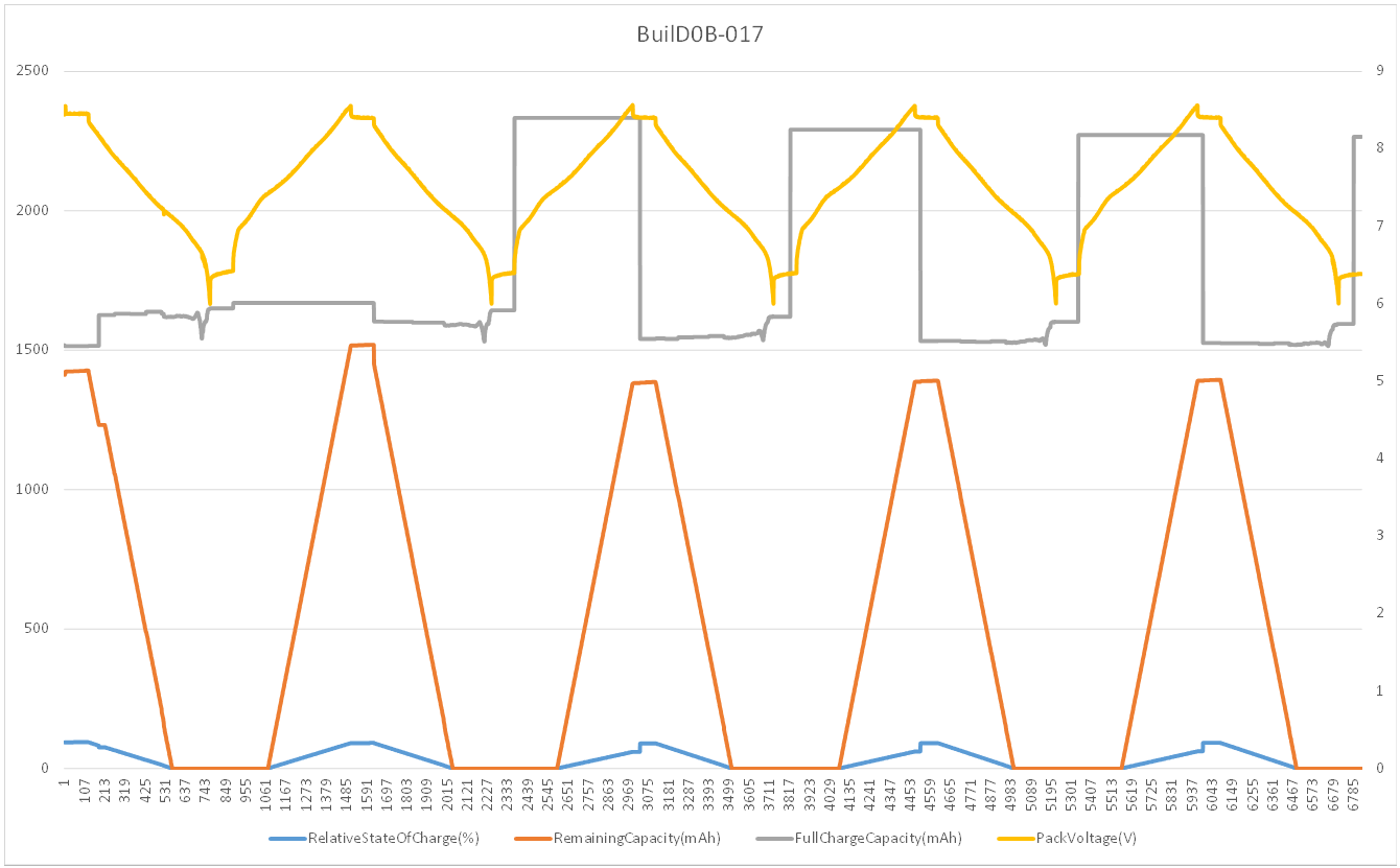
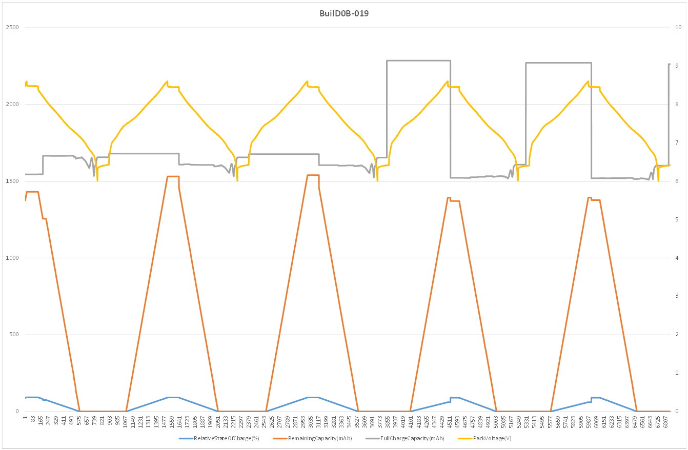
    I have a 2S1P packs with pack capacity of around 2500mAh . I have added the reserve capacity of 750mAh in the gg file so that the FCC as reported by the Smbus always stays below 2000mAh. When I cycle the pack, I am seeing the jumps in FCC in few packs as if the gauge forgot to account of the reserve capacity and the reported FCC value is around that 2500mAh range.  here is my question

    1. Why is the gauge reporting FCC of 2500mAh even when the reserve capacity of 750mAh is added? This new reserved capacity of 750mAh should always keep reported FCC below 2000mAH, so not sure why there is the jump in the gauge in FCC.

  • Hello Subrat,

    You will either need to change the reserve capacity and perform a gauge reset, or cycle the gauge for it to update the capacity. If you change the value of reserve capacity and do not perform one of the steps, on the first cycle the gauge will adjust, like you see in the logs.

    Generally when you change some of the settings and the batteries are in a relaxed state you should perform a reset so the values are implemented for gauging. When did you implement the change in the logs shared?

    Can you share the logs and the .gg files from this test?

    Sincerely,

    Wyatt Keller

  • Hi Wyatt,

    I can confirm that the reserve capacity was changed from 0mAh to 750mAh. Once this change was made, the pack underwent (PoR) power on reset where I shutdown the pack and wakeup the pack and verified the new reserve capacity was set.  Once this was verified, the pack was then cycled. 

    I am not being able to load the gg file and logs here as the website is not allowing me to upload my files. But to answer your question, the pack underwent PoR and the change is reserve capacity was verified

  • Hello Subrat,

    I will review further tomorrow and get back to you.

    Sincerely,

    Wyatt Keller

  • Hello Subrat,

    Can you share the error or what is preventing the logs from being shared? If they're too large you may need to split the log. Reviewing the data I think would be the most helpful in this case, along with the settings.

    The most common reason for FCC jumps is temperature change, the load select setting, or increased Ra table values. It could also be from the IT configuration settings that force the values at certain points, like CSYNC.

    Sincerely,

    Wyatt Keller

  • [Header]
    bq EVSW Version = 0.9.92
    DeviceName = bq30z554R1 v0.09
    Time = 2/24/2022 10:39:57 AM
    
    
    [State(Gas Gauging)]
    Qmax Cell 0 = 2581
    Qmax Cell 1 = 2581
    Qmax Cell 2 = 2500
    Qmax Cell 3 = 2500
    Qmax Pack = 2581
    Update Status = 0E
    Cell 0 Chg Voltage at EoC = 4197
    Cell 1 Chg Voltage at EoC = 4195
    Cell 2 Chg Voltage at EoC = 0
    Cell 3 Chg Voltage at EoC = 0
    Current at EoC = 131
    Avg I Last Run = -1253
    Avg P Last Run = -950
    Delta Voltage = 3
    Max Avg I Last Run = -1255
    Max Avg P Last Run = -1036
    [IT Cfg(Gas Gauging)]
    Load Select = 7
    Load Mode = 0
    Ra Filter = 50.0
    Ra Max Delta = 15
    Design Resistance = 24
    Reference Grid = 4
    Resistance Parameter Filter = 65142
    Term Voltage = 4500
    Term Voltage Delta = 500
    User Rate-mA = 0
    User Rate-cW = 0
    Reserve Cap-mAh = 750
    Reserve Cap-cWh = 0
    Remcap Smoothing Filter = 240
    Fast Scale Start SOC = 10
    [Turbo Cfg(Gas Gauging)]
    Min Turbo Power = 0
    Pack Resistance = 30
    System Resistance = 0
    Max Current Rate = -4
    High Frequency Resistance = 20
    Reserve Energy % = 2
    [Current Thresholds(Gas Gauging)]
    Dsg Current Threshold = 50
    Chg Current Threshold = 50
    Quit Current = 35
    
    [R_a0(Ra Table)]
    Cell0 R_a flag = 0000
    Cell0 R_a 0 = 35
    Cell0 R_a 1 = 37
    Cell0 R_a 2 = 41
    Cell0 R_a 3 = 49
    Cell0 R_a 4 = 35
    Cell0 R_a 5 = 35
    Cell0 R_a 6 = 42
    Cell0 R_a 7 = 31
    Cell0 R_a 8 = 118
    Cell0 R_a 9 = 118
    Cell0 R_a 10 = 184
    Cell0 R_a 11 = 310
    Cell0 R_a 12 = 770
    Cell0 R_a 13 = 6385
    Cell0 R_a 14 = 27791
    [R_a1(Ra Table)]
    Cell1 R_a flag = 0000
    Cell1 R_a 0 = 32
    Cell1 R_a 1 = 33
    Cell1 R_a 2 = 38
    Cell1 R_a 3 = 46
    Cell1 R_a 4 = 32
    Cell1 R_a 5 = 32
    Cell1 R_a 6 = 39
    Cell1 R_a 7 = 1
    Cell1 R_a 8 = 26
    Cell1 R_a 9 = 26
    Cell1 R_a 10 = 53
    Cell1 R_a 11 = 74
    Cell1 R_a 12 = 222
    Cell1 R_a 13 = 1805
    Cell1 R_a 14 = 7836
    [R_a2(Ra Table)]
    Cell2 R_a flag = FF55
    Cell2 R_a 0 = 66
    Cell2 R_a 1 = 71
    Cell2 R_a 2 = 80
    Cell2 R_a 3 = 111
    Cell2 R_a 4 = 94
    Cell2 R_a 5 = 74
    Cell2 R_a 6 = 82
    Cell2 R_a 7 = 75
    Cell2 R_a 8 = 80
    Cell2 R_a 9 = 92
    Cell2 R_a 10 = 145
    Cell2 R_a 11 = 234
    Cell2 R_a 12 = 628
    Cell2 R_a 13 = 5236
    Cell2 R_a 14 = 22706
    [R_a3(Ra Table)]
    Cell3 R_a flag = FF55
    Cell3 R_a 0 = 66
    Cell3 R_a 1 = 71
    Cell3 R_a 2 = 80
    Cell3 R_a 3 = 111
    Cell3 R_a 4 = 94
    Cell3 R_a 5 = 74
    Cell3 R_a 6 = 82
    Cell3 R_a 7 = 75
    Cell3 R_a 8 = 80
    Cell3 R_a 9 = 92
    Cell3 R_a 10 = 145
    Cell3 R_a 11 = 234
    Cell3 R_a 12 = 628
    Cell3 R_a 13 = 5236
    Cell3 R_a 14 = 22706
    [R_a0x(Ra Table)]
    xCell0 R_a flag = 0055
    xCell0 R_a 0 = 35
    xCell0 R_a 1 = 37
    xCell0 R_a 2 = 41
    xCell0 R_a 3 = 49
    xCell0 R_a 4 = 35
    xCell0 R_a 5 = 35
    xCell0 R_a 6 = 42
    xCell0 R_a 7 = 31
    xCell0 R_a 8 = 118
    xCell0 R_a 9 = 118
    xCell0 R_a 10 = 184
    xCell0 R_a 11 = 310
    xCell0 R_a 12 = 770
    xCell0 R_a 13 = 6385
    xCell0 R_a 14 = 27791
    [R_a1x(Ra Table)]
    xCell1 R_a flag = 0055
    xCell1 R_a 0 = 32
    xCell1 R_a 1 = 33
    xCell1 R_a 2 = 38
    xCell1 R_a 3 = 46
    xCell1 R_a 4 = 32
    xCell1 R_a 5 = 31
    xCell1 R_a 6 = 38
    xCell1 R_a 7 = 1
    xCell1 R_a 8 = 25
    xCell1 R_a 9 = 25
    xCell1 R_a 10 = 51
    xCell1 R_a 11 = 72
    xCell1 R_a 12 = 215
    xCell1 R_a 13 = 1749
    xCell1 R_a 14 = 7591
    [R_a2x(Ra Table)]
    xCell2 R_a flag = FFFF
    xCell2 R_a 0 = 66
    xCell2 R_a 1 = 71
    xCell2 R_a 2 = 80
    xCell2 R_a 3 = 111
    xCell2 R_a 4 = 94
    xCell2 R_a 5 = 74
    xCell2 R_a 6 = 82
    xCell2 R_a 7 = 75
    xCell2 R_a 8 = 80
    xCell2 R_a 9 = 92
    xCell2 R_a 10 = 145
    xCell2 R_a 11 = 234
    xCell2 R_a 12 = 628
    xCell2 R_a 13 = 5236
    xCell2 R_a 14 = 22706
    [R_a3x(Ra Table)]
    xCell3 R_a flag = FFFF
    xCell3 R_a 0 = 66
    xCell3 R_a 1 = 71
    xCell3 R_a 2 = 80
    xCell3 R_a 3 = 111
    xCell3 R_a 4 = 94
    xCell3 R_a 5 = 74
    xCell3 R_a 6 = 82
    xCell3 R_a 7 = 75
    xCell3 R_a 8 = 80
    xCell3 R_a 9 = 92
    xCell3 R_a 10 = 145
    xCell3 R_a 11 = 234
    xCell3 R_a 12 = 628
    xCell3 R_a 13 = 5236
    xCell3 R_a 14 = 22706
    
    [Manufacturer Data(System Data)]
    ManufacturerInfo = EXXXXXX-XXX
    [Integrity(System Data)]
    Data Flash Checksum = 0000
    
    [Data(SBS Configuration)]
    Remaining AH Cap. Alarm = 300
    Remaining WH Cap. Alarm = 432
    Remaining Time Alarm = 10
    Initial Battery Mode = 0081
    Design Voltage = 7200
    Specification Information = 0031
    Manufacture Date = 09-Sep-2020
    Serial Number = 0030
    Cycle Count = 16
    Cycle Count Percentage = 100
    Max Error Limit = 100
    Design Capacity mAh = 2500
    Design Capacity cWh = 1800
    Manufacturer Name = Medtronic
    Device Name = PT00112272
    Device Chemistry = LION
    [FD(SBS Configuration)]
    Set Voltage Threshold = 3000
    Clear Voltage Threshold = 3100
    Set % RSOC Threshold = 0
    Clear % RSOC Threshold = 5
    [FC(SBS Configuration)]
    Set Voltage Threshold = 4200
    Clear Voltage Threshold = 4100
    Set % RSOC Threshold = 100
    Clear % RSOC Threshold = 95
    [TDA(SBS Configuration)]
    Set Voltage Threshold = 2900
    Clear Voltage Threshold = 3000
    Set % RSOC Threshold = 10
    Clear % RSOC Treshold = 15
    [TCA(SBS Configuration)]
    Set Voltage Threshold = 4250
    Clear Voltage Threshold = 4125
    Set % RSOC Threshold = 100
    Clear % RSOC Threshold = 95
    [Max Error(SBS Configuration)]
    Time Cycle Equivalent = 254
    Cycle Delta = 0.05
    
    [CUV(Protections)]
    Threshold = 2800
    Delay = 10
    Recovery = 3200
    [CUVC(Protections)]
    Threshold = 2900
    Delay = 6
    Recovery = 3200
    [COV(Protections)]
    Threshold Low Temp = 4200
    Threshold Standard Temp = 4250
    Threshold High Temp = 4250
    Threshold Rec Temp = 4250
    Delay = 2
    Recovery Low Temp = 4000
    Recovery Standard Temp = 4050
    Recovery High Temp = 4050
    Recovery Rec Temp = 4050
    [OCC1(Protections)]
    Threshold = 2000
    Delay = 6
    [OCC2(Protections)]
    Threshold = 2500
    Delay = 3
    [OCC(Protections)]
    Recovery Threshold = 50
    Recovery Delay = 5
    [OCD1(Protections)]
    Threshold = -16000
    Delay = 10
    [OCD2(Protections)]
    Threshold = -20000
    Delay = 6
    [OCD(Protections)]
    Recovery Threshold = -50
    Recovery Delay = 5
    [OLD(Protections)]
    Threshold = 0F
    Delay = 0F
    Latch Limit = 0
    Counter Dec Delay = 10
    Recovery = 5
    Reset = 15
    [SCC(Protections)]
    Threshold = 10
    Latch Limit = 0
    Counter Dec Delay = 10
    Recovery = 5
    Reset = 15
    [SCD1(Protections)]
    Threshold = 73
    [SCD2(Protections)]
    Threshold = 34
    [SCD(Protections)]
    Latch Limit = 0
    Counter Dec Delay = 10
    Recovery = 5
    Reset = 15
    [OTC(Protections)]
    Threshold = 55.0
    Delay = 2
    Recovery = 50.0
    [OTD(Protections)]
    Threshold = 60.0
    Delay = 2
    Recovery = 55.0
    [OTF(Protections)]
    Threshold = 80.0
    Delay = 2
    Recovery = 65.0
    [HWD(Protections)]
    Delay = 10
    [PTO(Protections)]
    Charge Threshold = 1150
    Suspend Threshold = 1000
    Delay = 1800
    Reset = 2
    [CTO(Protections)]
    Charge Threshold = 2500
    Suspend Threshold = 2000
    Delay = 14400
    Reset = 2
    [OC(Protections)]
    Threshold = 350
    Recovery = 2
    RSOC Recovery = 90
    [CHGV(Protections)]
    Threshold = 500
    Delay = 30
    Recovery = -500
    [CHGC(Protections)]
    Threshold = 500
    Delay = 2
    Recovery = 100
    
    [CUV(Permanent Fail)]
    Threshold = 2000
    Delay = 2
    [COV(Permanent Fail)]
    Threshold = 4300
    Delay = 2
    [CUDEP(Permanent Fail)]
    Threshold = 2000
    Delay = 2
    [OTCE(Permanent Fail)]
    Threshold = 65.0
    Delay = 2
    [OTF(Permanent Fail)]
    Threshold = 90.0
    Delay = 2
    [CB(Permanent Fail)]
    Max Threshold = 240
    Delta Threshold = 40
    Delay = 2
    [VIMR(Permanent Fail)]
    Check Voltage = 3500
    Check Current = 10
    Delta Threshold = 200
    Delta Delay = 2
    Duration = 100
    [VIMA(Permanent Fail)]
    Check Voltage = 3700
    Check Current = 50
    Delta Threshold = 300
    Delay = 2
    [CD(Permanent Fail)]
    Threshold = 1550
    Delay = 2
    [CFET(Permanent Fail)]
    OFF Threshold = 20
    OFF Delay = 2
    [DFET(Permanent Fail)]
    OFF Threshold = -20
    OFF Delay = 2
    [TH(Permanent Fail)]
    ADC Delay = 10
    [FUSE(Permanent Fail)]
    Threshold = 5
    Delay = 2
    [AFER(Permanent Fail)]
    Threshold = 100
    Delay Period = 2
    Compare Period = 5
    [AFEC(Permanent Fail)]
    Threshold = 100
    Delay Period = 5
    [2LVL(Permanent Fail)]
    Delay = 2
    [OCECO(Permanent Fail)]
    Threshold = 5000
    Delay = 2
    
    [Device Status Data(PF Status)]
    Safety Alert 0-15 = 0000
    Safety Status 0-15 = 0000
    PF Alert 0-15 = 0000
    PF Status 0-15 = 0000
    Safety Alert 16-31 = 0000
    Safety Status 16-31 = 0000
    PF Alert 16-31 = 0000
    PF Status 16-31 = 0000
    Operation Status 0-15 = 7101
    Operation Status 16-31 = 0010
    Charging Status 0-15 = 0208
    Charging Status 16-23 = 00
    Gauging Status = 0012
    [Device Voltage Data(PF Status)]
    Cell Voltage 0 = 3899
    Cell Voltage 1 = 3916
    Cell Voltage 2 = 0
    Cell Voltage 3 = 0
    Battery Direct Voltage = 15404
    Pack Voltage = 119
    [Device Current Data(PF Status)]
    Current = 13
    [Device Temperature Data(PF Status)]
    Internal Temperature = 24.1
    External 1 Temperature = 24.6
    External 2 Temperature = 25.0
    [Device Gauging Data(PF Status)]
    Cell0 Dod0 = 3712
    Cell1 Dod0 = 3456
    Cell2 Dod0 = 0
    Cell3 Dod0 = 0
    Passed Charge = 0
    [AFE Regs(PF Status)]
    AFE Status = 00
    AFE State Control = 00
    AFE Control = 00
    AFE Output Status = 00
    AFE Function Control = 00
    AFE Cell Select = 00
    AFE OCDV = 0F
    AFE OCDT = 0F
    AFE SCC = 10
    AFE SCD1 = 73
    AFE SCD2 = 34
    AFE REF TRIM = 0E
    
    [Safety Status(Black Box)]
    1st Status Status 0-15 = 0000
    1st Safety Status 16-31 = 0000
    1st Time to Next Event = 0
    2nd Safety Status 0-15 = 0000
    2nd Safety Status 16-31 = 0000
    2nd Time to Next Event = 0
    3rd Safety Status 0-15 = 0000
    3rd Safety Status 16-31 = 0000
    3rd Time to Next Event = 0
    [PF Status(Black Box)]
    1st PF Status 0-15 = 0000
    1st PF Status 16-31 = 0000
    1st Time to Next Event = 0
    2nd PF Status 0-15 = 0000
    2nd PF Status 16-31 = 0000
    2nd Time to Next Event = 0
    3rd PF Status 0-15 = 0000
    3rd PF Status 16-31 = 0000
    3rd Time to Next Event = 0
    
    [Voltage(Lifetimes)]
    Max Cell Voltage 0 = 4200
    Max Cell Voltage 1 = 4200
    Max Cell Voltage 2 = 0
    Max Cell Voltage 3 = 0
    Min Cell Voltage 0 = 2580
    Min Cell Voltage 1 = 2640
    Min Cell Voltage 2 = 0
    Min Cell Voltage 3 = 0
    Max Delta Cell Voltage = 60
    [Current(Lifetimes)]
    Max Charge Current = 1200
    Max Discharge Current = 1200
    Max Avg Dsg Current = 1200
    Max Avg Dsg Power = 10
    [Safety Events(Lifetimes)]
    No Of Cov Events = 0
    Last Cov Event = 0
    No Of Cuv Events = 32
    Last Cuv Event = 12
    No Of Ocd1 Events = 0
    Last Ocd1 Event = 0
    No Of Ocd2 Events = 0
    Last Ocd2 Event = 0
    No Of Occ1 Events = 0
    Last Occ1 Event = 0
    No Of Occ2 Events = 0
    Last Occ2 Event = 0
    No Of Old Events = 0
    Last Old Event = 0
    No Of Scd Events = 0
    Last Scd Event = 0
    No Of Scc Events = 0
    Last Scc Event = 0
    No Of Otc Events = 0
    Last Otc Event = 0
    No Of Otd Events = 0
    Last Otd Event = 0
    No Of Otf Events = 0
    Last Otf Event = 0
    [Charging Events(Lifetimes)]
    No Valid Charge Term = 8
    Last Valid Charge Term = 12
    [Gauging Events(Lifetimes)]
    No Of Qmax Updates = 16
    Last Qmax Update = 12
    No Of Ra Updates = 304
    Last Ra Update = 12
    No Of Ra Disable = 8
    Last Ra Disable = 12
    [Power Events(Lifetimes)]
    No Of Shutdowns = 4
    [Cell Balancing(Lifetimes)]
    Cb Time Cell 0 = 0
    Cb Time Cell 1 = 2
    Cb Time Cell 2 = 0
    Cb Time Cell 3 = 0
    [Temperature(Lifetimes)]
    Max Temp Cell = 28
    Min Temp Cell = 20
    Max Delta Cell Temp = 3
    Max Temp Int Sensor = 26
    Min Temp Int Sensor = 18
    Max Temp Fet = 27
    [Time(Lifetimes)]
    Total Fw Runtime = 816
    Time Spent In UT = 0
    Time Spent In LT = 0
    Time Spent In STL = 0
    Time Spent In RT = 776
    Time Spent In STH = 34
    Time Spent In HT = 0
    Time Spent In OT = 0
    
    [Fuse(Settings)]
    PF Fuse 0-15 = 0000
    PF Fuse 16-31 = 0000
    Min Blow Fuse Voltage = 5000
    [Manufacturing(Settings)]
    Manufacturing Status = 01F8
    [Protection(Settings)]
    Enabled Protections 0-15 = FFFF
    Enabled Protections 16-31 = FFFD
    [Permanent Failure(Settings)]
    Enabled PF 0-15 = EEFB
    Enabled PF 16-31 = FFFF
    [Configuration(Settings)]
    Protection Configuration = 01
    Temperature Configuration = 1087
    Charging Configuration = 21
    System Configuration = 0235
    Gauging Configuration = 37DE
    Sbs Configuration = 20
    Sbs Data Config. 0-15 = 0C2F
    Sbs Data Config. 16-23 = FF
    [AFE(Settings)]
    AFE State Control = 00
    
    [Power(Power)]
    Valid Update Voltage = 4500
    [Shutdown(Power)]
    Shutdown Voltage = 2600
    Shutdown Time = 1
    Charger Present Threshold = 3000
    [Sleep(Power)]
    Sleep Current = 10
    Voltage Time = 5
    Current Time = 20
    Wake = 02
    [Ship(Power)]
    Delay = 1
    [Power Off(Power)]
    Timeout = 30
    Debounce = 4
    
    [Temperature Ranges(Advanced Charge Algorithm)]
    T1 Temp = 0
    T2 Temp = 12
    T5 Temp = 20
    T6 Temp = 25
    T3 Temp = 50
    T4 Temp = 55
    Hysteresis Temp = 0
    [Low Temp Charging(Advanced Charge Algorithm)]
    Voltage = 4100
    Current Low = 400
    Current Med = 500
    Current High = 600
    [Standard Temp Charging(Advanced Charge Algorithm)]
    Voltage = 4200
    Current Low = 1150
    Current Med = 1150
    Current High = 1150
    [High Temp Charging(Advanced Charge Algorithm)]
    Voltage = 4200
    Current Low = 1150
    Current Med = 1150
    Current High = 1150
    [Rec Temp Charging(Advanced Charge Algorithm)]
    Voltage = 4200
    Current Low = 1150
    Current Med = 1150
    Current High = 1150
    [Pre-Charging(Advanced Charge Algorithm)]
    Current = 320
    [Maintenance Charging(Advanced Charge Algorithm)]
    Current = 320
    [Voltage Range(Advanced Charge Algorithm)]
    Charging Voltage Low = 2900
    Charging Voltage Med = 3600
    Charging Voltage High = 4000
    Charging Voltage Hysteresis = 0
    [Termination Config(Advanced Charge Algorithm)]
    Charge Term Taper Current = 150
    Charge Term Voltage = 75
    [Cell Balancing Config(Advanced Charge Algorithm)]
    Bal Time/mAh Cell 0 = 367
    Bal Time/mAh Cell 1-3 = 514
    Min Start Balance Delta = 10
    Relax Balance Interval = 18000
    Min Rsoc for Balancing = 50
    [Charging Rate of Change(Advanced Charge Algorithm)]
    Current Rate = 1
    Voltage Rate = 1
    [Charge Loss Compensation(Advanced Charge Algorithm)]
    CCC Current Threshold = 2000
    CCC Voltage Threshold = 4200
    
    [Voltage(Calibration)]
    Cell Scale 0 = 20568
    Cell Scale 1 = 20618
    Cell Scale 2 = 20520
    Cell Scale 3 = 20517
    Pack Gain = 54735
    BAT Gain = 48546
    [Current(Calibration)]
    CC Gain = 1.724
    Capacity Gain = 514143.469
    [Current Offset(Calibration)]
    CC Offset = -8233
    Coulomb Counter Offset Samples = 64
    Board Offset = 64
    [Temperature(Calibration)]
    Internal Temp Offset = 7.0
    External1 Temp Offset = -1.0
    External2 Temp Offset = -1.4
    [Internal Temp Model(Calibration)]
    Int Coeff 1 = 0
    Int Coeff 2 = 0
    Int Coeff 3 = -11136
    Int Coeff 4 = 5754
    Int Minimum AD = 0
    Int Maximum Temp = 5754
    [Cell Temperature Model(Calibration)]
    Coeff a1 = -14520
    Coeff a2 = 23696
    Coeff a3 = -20298
    Coeff a4 = 28073
    Coeff a5 = 865
    Coeff b1 = -694
    Coeff b2 = 1326
    Coeff b3 = -3880
    Coeff b4 = 5127
    Rc0 = 11703
    Adc0 = 11703
    Rpad = 0
    Rint = 0
    [Fet Temperature Model(Calibration)]
    Coeff a1 = -14520
    Coeff a2 = 23696
    Coeff a3 = -20298
    Coeff a4 = 28073
    Coeff a5 = 865
    Coeff b1 = -694
    Coeff b2 = 1326
    Coeff b3 = -3880
    Coeff b4 = 5127
    Rc0 = 11703
    Adc0 = 11703
    Rpad = 0
    Rint = 0
    [Filter(Calibration)]
    Cell Voltage 1 = 145
    Cell Voltage 2 = 145
    Cell Voltage 3 = 145
    Cell Voltage 4 = 145
    Pack Voltage Out = 10
    Direct Battery Voltage = 10
    Summed Battery Voltage = 145
    Cell Temperature = 145
    FET Temperature = 145
    [Current Deadband(Calibration)]
    Deadband = 2
    Coulomb Counter Deadband = 34
    

    Hi Wyatt,

    I am still having issues with attaching the files in this thread directly. I have used text code format to copy the gg file I used in this thread. Can you provide me with your email, so I can share the link with cycling logs data.

    Sincerely,

    Subrat  

  • Hello Subrat,

    You may have to break the files into 2 section if they are very large, or just grab a block of the bad FCC update and good FCC update.

    I would review your Gauging Configuration register and make sure that none of the enabled features could be causing the jump (either by holding ROSC or by actual simulation calculations)

    Sincerely,

    Wyatt Keller

  • E030 gg file.gg.xlsx

    E030 cycling run 3 Maccor data -increased rest time-.014.xlsx

    E030 cycling run 3 Maccor data -increased rest time-.014.xlsx

    Hi Wyatt,

    Attached is the Cycling data used along side all the smbus information including Gauging status and IT status register data as well as gg file. 

  • Hello Subrat,

    I will review the data today and get back to you with further feedback.

    Sincerely,

    Wyatt Keller

  • Hello Subrat,

    Your gauging config is 0x37DE which means you still have CYSNC enabled, can you try testing with this disabled to check the operation. This feature can cause jumps in RemCap for some cases which is happening in your logs. This may be fixed by resolving the FCC jump but just wanted to mention it again.

    The FCC jumps may be from the current it's using for simulation, can you try changing your load select to 1? This may help with the jumps since the sim will be based on the average current.

    Sincerely,

    Wyatt Keller

  • Hi Wyatt,

    I made the changes you suggested and performed with load select of 1. That did not resolve the issue. I found this on e2e thread from 4 years back where this customer was also having a very similar issue to what i am facing here and observing this FCC jump. Here is the link attached. Can you let me know how that situation was resolved.

    e2e.ti.com/.../bq20z655-r1-rc-fcc-too-high-when-using-reserve-capacity-feature

  • Hello Subrat,

    I would recommend that you start afresh. Import the GG file. set the correct reserve capacity, program chemistry and then run the learning cycle. I suspect that the gauge "learned" data based on the different reserve capacity. The learning process is complex and we may not be able to pinpoint the data that is causing issues.

  • Hi Shirish,

    Thanks for the reply, Are you able to find how the issue in the link I posted below was resolved.

    I am certain that solution should work in our case as well.

    e2e.ti.com/.../bq20z655-r1-rc-fcc-too-high-when-using-reserve-capacity-feature

  • Hello Subrat,

    There is no documentation available on how the other thread was resolved since it was handled privately.