This thread has been locked.

If you have a related question, please click the "Ask a related question" button in the top right corner. The newly created question will be automatically linked to this question.

UCC28070: TI TINA Example UCC28070_trans

Part Number: UCC28070

Dear all,

using the TI TINA example UCC28070_trans for simulating a PFC I have several questions:

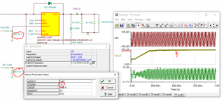
- First of all, the example works with the given load. But when I change the load to 250 Ohm (about 600W) the output voltage does not reach 400V any more. Why does it behaves like this?

- Why is there a high inrush current @I_In of 6kA although using Bypass-diode D5

- Where do I find a inner schematic of the blocks "boot_AVG"? What is the Input "CSOFFX"?

The example I attached.

UCC28070_AVG.TSC

Now I have a general question for TI TINA:

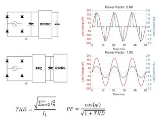
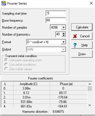
- How can I calculate a power factor when having V_In and I_In?

I use TINA 9.3.200

Regards and thank you for helping me!

Andreas

  • Hi Andreas,

    Thank you for your interest in the UCC28070.

    I was unable to get your attached sim to run without errors (I'm also running v9.3.200).  I downloaded the TINA model from TI.com and changed Rload to 250Ω and I see it regulating up to ~395V, the same as it does with the default 531Ω load.  Also, I don't see a large surge current on Ivin.  Perhaps you can start with a clean simulation and try once again.   You may also want to try the PSPICE model (https://www.ti.com/lit/zip/slum097)

    Without and NDA, TI doesn't supply the unencrypted data inside the macros. I looked at it and it appears to be adding the offset to the current sense signal as outlined in sec 8.2.2.8 in the datasheet.

    PF cannot be calculated by simply measuring V_in and I_in.  PF has two major components: the phase angle between V_in and I_in and the distortion of those signal(s) (THD).  The following screenshot provides a good representation of PF correction from a signal with both signal distortion as well as a phase offset. PF equations are at the bottom. If you had no distortions in the voltage or current signals, you could calculate the PF as simply the cosine of the phase displacement between current and voltage.

    I hope this helps.

    Best Regards,
    Ray

  • Hi Ray,

    thanks for your good help. I download the file from https://www.ti.com/lit/tsc/slum328 and it works for 155Vpeak and 365Vpeak at V_In. But when I change the load from 531R to 250R it works only for 365Vpeak input. When using 155Vpeak at the input (US-grid) the output voltage fall down to about 300V. Why is this behaviour?

    I understand the topic referring the power factor. I use the fourier analysis of the I_In graph and select only the time from 2s to 3s (stable state). I attached the different results for 365Vpeak and 155Vpeak with 531R load. Should the PFC works for both cases the same?

    Kind regards

    Andreas

  • Hi Andreas,

    I see the issue.  Because this was designed for 300W, you have to adjust the current sense resistor to accommodate the higher current with the 250Ω load (640W).  I simply halved the resistors (R20 and R22).  You must also change the CSGAIN parameter to 16.1/50 = 0.32 (see instruction #7 at the bottom of the sim page).  Now you're not hitting the current limit and the output can regulate up to 400V.

    Give that a try and see how your PF results look.

    Regards,
    Ray

  • Hi Ray, thanks for your good and quick help. Now it works! Regards Andreas