This thread has been locked.

If you have a related question, please click the "Ask a related question" button in the top right corner. The newly created question will be automatically linked to this question.

BQ20Z80A-V110 & BQ29312A

Other Parts Discussed in Thread: BQ20Z80A-V110, BQ20Z80

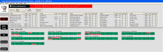
I am using the bq20z80a-v110 evaluation board and im having issues. After going through the bqEASY setup i get to the charge/discharge portion but i cant charge or discharge because the FETS stay inactive (first sceenshot below). So i then write the command to turn on the FETS and it says that there is a short in the discharge direction however there is no load attached to the eval board (second screenshot below). One thing i did notice is that when i read the data flash info some of the setting dont seem to match what i thought would have been written to flash via the bqeasy. Can anyone please give a little insight to what might cause the chip to see a short without one being present?

  • The FETs won't automatically turned on unless you enable IT. It didn't look like the case from the screen shot.

    Not sure if you went through all the steps in bqEASY. To properly evaluate the performance of the device, besides configuring the data flash, you also have to calibrate the pcb, program the chemistry, and run a learning cycle to learn the battery's Qmax and resistance.


    If you see the DF is not configured correctly according to the bqEASY input, that could be the reason a SCD flag is set.

    Which settings are not updated properly? Can you provide a gg file and a .ezy file for comparison?

    Also please provide bigger/higher resolution screen shot. I can hardly see anything from the attached pictures.


  • Jackie,

    Thanks for the response! I went through the entire bqEASY (v1.87) setup (as far as i could). I did the following:

    1. Read in the device default .dfi file. (bq20z80_1_10.dfi)
    2. Input all of the setting to be programmed into DF.
    3. Calibrated voltage, and some what the current i think. i wasnt able to get the FETS to work properly so i dont know exactly. Initially the pcb was reading 4ma with no load or power supply attached, so in the measured current i put 0 ma. This seemed to calibrated out the 4 ma reading.
    4. Did the chemistry selection
    5. The learning cycle is where the trouble began, since the FETS dont work correctly i cant charge or discharge. I tried to enable them manually by writing 46 to 0006, but then i see the situation descirbed in the previous post.


  • Jackie,

    i attached the .ezy file to one post and the .gg file to this post.


    When i said that certain things didnt seem to be getting programmed correctly in the DF i meant things such as the OC (1st tier) chg got set to 26000ma, but in the bq20z80 tech ref is says that the max value for this is 20000ma, and i dont think anything i did caused this to get set this way.


  • Kevin,


    Looked like you did the CC offset calibration, which calibrated out the 4mA. How about current gain calibration? Did you apply -2A to calibrate current gain? You don't need to turn on the FETs, you can apply the -2A between PACK- and BAT-, which will put the current directly through the sense resistor.


    Now, bqEASY configure OC parameter by taking NormCapacity * No. of parallel cell * 1.25. From the ezy file, your # of parallel cell is 8. Is this correct? You have a 4S8P pack (i.e. 32 cells in total!?). Now, when you see the OC fault, what was the current you apply to the pcb?


    When you said the FETs was not turned on, did you enable IT? As I mentioned, the screen shot suggested IT was not enabled.

  • Jackie,


    yes the cell pack is 32 cells, 4s8p, and there was no current applied to the pcb when the fault occured. It occurs when i use the pro screen to enable the FETs (i used to be able to reset the board using the pro screen after the fault condition but i no longer can). I still dont understand how that OC setting could be higher than the maximum allowed?

    I tried to enable IT two ways, first by the initialize button in the bqEASY, and then also by using the pro screen to enable IT, but neither seems to do anything.

    I have been reading alot of the posts on the forums and some people have issues when they have the wrong version of bqeasy, or the wrong .senc file etc...how would i know if this is the case? 

    im using this version of the bqeasy:

    bqEVSWSetup00.09.65_bq20z80v1.10.exe

  • You're right, the problem could be because of the 20A limit. On the newer devices, the current limit is higher (32A)

    In that case, you will have to "fool" the z80 by calibrating with a smaller current. For example, by inputting -2A in the current calibration screen, while actually applying -4A to calibrate current. You will have to change all current related parameters and the design capacity and Qmax into 1/2 as well.

  • Jackie,

    I found the problem, it was the power supply i was using to charge the pack. It seems that there is a momentary short when you power up the power supply and the bq chip sensed that and shut it down. The way i tested was to have the power supply on before connecting the bq board to it and this resolved the issue, i can charge and discharge normally.

    So i guess the OC parameter i was mentioning before may not be an issue after all?

    Thanks

    Kevin