This thread has been locked.

If you have a related question, please click the "Ask a related question" button in the top right corner. The newly created question will be automatically linked to this question.

LM5102: LM5102

Part Number: LM5102

Hello,

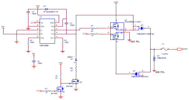
I use the LM5102 driver to drive High Side and Low Side MOS according to the attached diagram.

In simulation it works perfectly.

In real life it's another thing.

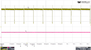
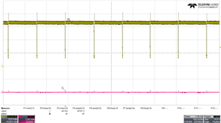
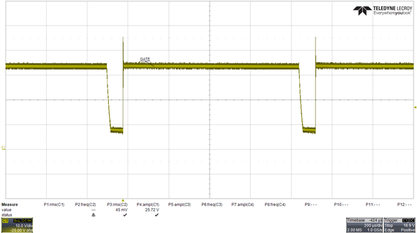
The gate of the High side MOS oscillates periodically.

To make it work I use a 15V Dc/Dc converter between pin 2 and 4 of the LM5102, but LOW Side not work witth this solution.
It's not a good solution

Thanks for your help.


I only drive the high side (pin7 de U1=5V), oscillation en G1.

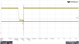
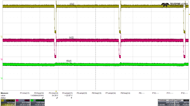
Power DC/DC +15V between pins 2 and 4

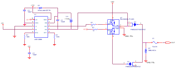
Result OK for the high side, but the low side does not work anymore

  • Hi,

    Thank you for posting your question on E2E. In order to further assist you can you provide the following information?

    Are the driver inputs being oscillated or are they always set as shown in the schematic? (high side high, low side ground)

    Does the operation of the low side gate change when the 15V converter is added to the system?

    Please include a scope shot with the driver pins HI, LI, HO and LO in order to be able to see the on and off timings and behavior.

    Thanks,

    Daniel W

  • Hi,

    Yes only the high side oscillated.

    When the 15V is added the high side operation is correct but the low side does not work
    You will find attached the scope readings

    High Side driver

    HO yellow

    HI red=5V

    HO yellow

    LI=0V

    Zoom HO et HI

    The low side works correctly if I don't add a DC +15V source (pin 2 and pin 4), I didn't do a scope reading

    The problem is the operation of the High Side

    Thanks for your help

  • Hi,

    Thank you for the information. I will review this and get back to you with more information tomorrow.

    Thanks,

    Daniel W

  • Hi,

    In order to have the high side driver operate without the added voltage source, it is likely the bootstrap circuitry may need adjustment.

    I would recommend reviewing the linked app note to ensure you have the correct bootstrap circuitry in place to drive your high side FET, particularly please review the bootstrap capacitor.

    https://www.ti.com/lit/an/slua887/slua887.pdf

    Additionally, the diodes connecting the 2 FETs may be causing enough of a voltage drop that the bootstrap capacitor may not charge enough.

    Please review these suggestions and let me know if you have any further questions.

    Thanks,

    Daniel W

  • Hi,

    If you look at the diagram above, I don't drive the low side MOS, the charge current of the boostrap capacitor goes through the bas21 diode, the 10K resistor and the 2N7002 transistor.

    The LI control of the LM5102 circuit is always at 0V.

    Is it possible to operate the circuit in these conditions? In simulation it does not break any problem.

    Thanks,

    YD

  • Hi YD,

    Sorry for the confusion.

    If the goal is to keep the low side always off then why is it an issue if it is not working?

    In order to further investigate the bootstrap system I would recommend a scope shot of HB wrt HS. This will provide further insight if the goal is to be able to operate the circuit without the additional voltage supply.

    Thanks,

    Daniel W

  • Hi,

    We don't understand, my English is too bad.
    I want to make work  the Hide side only.

    See the simulation design.LM5102.zip

    Green HB HS

    Yellow Vout

    Red GATE

  • Hi,

    Thank you for the clarification.

    Should the high side output always be high?

    It appears that HB-HS goes under the device UVLO range and the device makes the output low. This allows the capacitor to charge and HB-HS goes high enough to make the output high again.

    Please see the "Startup and UVLO" section of the datasheet for more information.

    Thanks,

    Daniel W

  • Hi,

    Yes the high side is still active.

    Right Vhb-Vhs can be less than 6.9V. What to do on this design so that Vhb-Vhs is always > 6.9V

    Why the problem is not found in simulation?

    Thanks.

  • Hi,

    The high side driver cannot be on forever without an external power supply. Current leaks from the bootstrap capacitor through the high side driver. In order to keep the high side driver on, a charge pump or similar circuit is needed.

    I can follow up with the team to see why the simulation does not show this

    Thanks,

    Daniel W