This thread has been locked.

If you have a related question, please click the "Ask a related question" button in the top right corner. The newly created question will be automatically linked to this question.

LM3409: External PWM for strobing

Part Number: LM3409

Hi,

I'm using the LM3409EVAL and am not getting the results that I am expecting. I wanted to test the possiblity driving the shunt FET externally as specified in the datasheet, and modified the circuit in this manner (roughly)

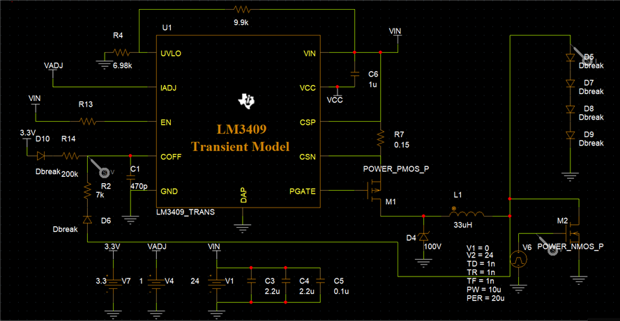
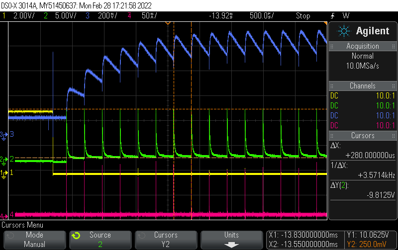
The simulation provides an off-time of about 300ns, but on the eval board it goes into maximum off-time (300us). Is there anything I'm missing in this setup?

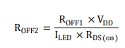
Roff1(R2) and Roff2(R14) were calculated according to the datasheet, the rest is similar to the eval board.

  • Hello Altin,

    R14 time constant is 94 us,  It's still more than 300 us so there may be something else wrong but R14 resistor value is probably too high.  I would also check diode orientation for D10 to make sure it is installed correct.  You should be able to watch the Coff pin and watch it charge with an oscilloscope.

    If you give me all of your operating parameters, Vin (and range), Vled (and range), Iled (and range) including Viadj levels, D4 and M1 part numbers or specifications.

    Best Regards,

  • Hello Irwin,

    Thanks for your answer. I calculated R14 through this equation

    With arbitrary current to 1A. But to be completely honest I am not sure if I understood exactly the implication of this second time constant. I checked the diode and even tried both ways in case I was blind but no difference. Regarding M1 and D4 it is the ones mounted on the eval, meaning (PMOS 100V 3.8A) ZETEX ZXMP10A18KTC and (Schottky 100V 3A) VISHAY SS3H10-E3/57T. I took a picture from the oscilloscope where you can see some parameters where I extended the pulse (Yellow) to illustrate the behavior. (Vin=24V, Vout=~10V (4LEDS), Iled=up to 1A).

    (Yellow=M2 pulse)(Green=VLED)(Blue=Voltage at COFF)(Pink=LED current)

  • Hello Altin,

    I'll look closer at this tomorrow, today was a day off.  The output voltage is not high enough for it to run at 200 mV/div.  It seems something is limiting Coff from charging to 1.243V.

    Best Regards,

  • Alright, I also think it is strange. If you see anything obvious it would be of great benefit.

  • Hello Altin,

    The off-time waveform looks incorrect.  If it is off it should be charging Coff through your 3.3V.  It appears something is pulling it down.  Is D6 installed and in the correct orientation?  You can try removing R2 to see if the off-time starts working correct when the output is shunted.

    Best Regards,

  • Okay, yes it should be. I tested removing R2 but in that case Coff voltage is close to gnd. I checked resistance from Coff pin to gnd and it was about 11kOhm, which seems to explain it perhaps. Is this really as it should be?

  • Hello Altin,

    If Coff is only connected to the 200 Kohm and diode it should get pulled up unless something is telling the LM3409 to pull Coff low.  If you measure through the points on your schematic, 3.3V at D10 anode, D10 cathode/R14 and then the Coff pin does it make sense?  Also verify that Coff is actually 470 pF.  You can reduce R14 to a lower value as well however it should still be pulled up by the 200 Kohm.

    Best Regards,

  • Coff is only acting as a 11kOhm resistance to ground no matter what is attached to it. This is when the feedback from the inductor is de-attached. Voltage, diode orientation or resistance has no impact.
    Would you say it is safe to assume the IC is faulty, meaning the implementation should be working this way theoretically?

  • Altin,

    If 3.3V through R14 is not charging COFF up to 1.234V, then replace the IC and test again.  There should be nothing preventing this operation.  I'm of course assuming you have VIN above VIN_UVLO set at the UVLO pin and you have EN high.  Also, make sure your VCC is correct (referenced from VIN of course).  

    -JP

  • OK, thank you for your answer. That seems like a good conclusion. I will check this but finding a replacement is tricky in this situation unfortunately. 
    Also, thanks Irwin for your help.