This thread has been locked.

If you have a related question, please click the "Ask a related question" button in the top right corner. The newly created question will be automatically linked to this question.

LM5113: Bootstrapping current path in spice model

Part Number: LM5113

Hi,

I am working on a TINA simulation to use LM5113 for driving a synchronous boot converter.

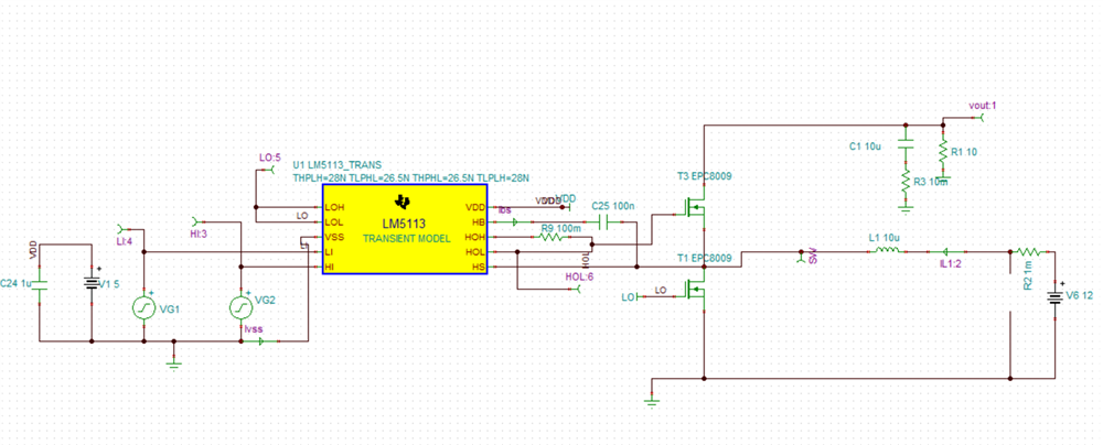
The circuit is working fine and i am able to generate an output voltage.

But i am interested in understanding the bootstrapping current path.

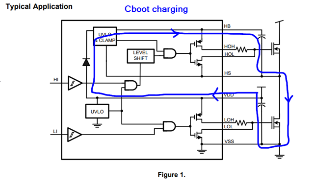
I believe that the bootstrapping capacitor C25 should be charged by the 5V Vdd supply when bottom switch is on.

However, i see a large current entering the Vss pin (IVss) which matches the bootstrapping current (Ibs) when the bottom switch is turned on.

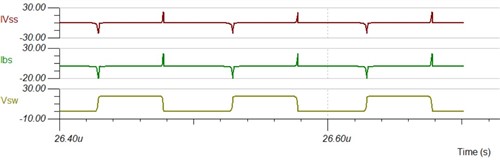
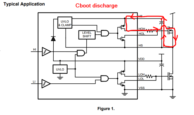
Comparing this result to the internal block diagram of LM5113 i am not able to follow the bootstrapping current path. Can you please explain why i am seeing large current input in the Vss pin.

Additionally, as already mentioned in multiple threads (https://e2e.ti.com/support/power-management-group/power-management/f/power-management-forum/490283/lm5113-falling-edge-spikes)

i am seeing falling edge spikes that does not make much sense.

I am attaching my Tina Simulation with this thread for reference.

Lm5113_Boost.TSC

Thanks

Ankit


  • Hi Ankit, 

    Thank you for your question. This application note, section 2 explains the charge and discharge path of the bootstrap circuit, specifically figures 1 and 2. 

    https://www.ti.com/lit/an/slua887/slua887.pdf

    Regarding the falling edge spikes, I'm not able to open the link you copied. Could you please provide details on what the issue is?

    Best regards,

    Leslie

  • Hi Leslie,

    Yes my understanding about the charging and discharging path for bootstrap is concurrent to what is mentioned in the application note. However, this is not what  am seeing in the spice model. As i mentioned, IVss is the current entering the gate driver (pin 4 in fig 1 of the app note you referred) and Ibs is the current entering the bootstrap capacitance. As seen in Fig.1 the bootstrapping current should not enter the GD through pin 4 and should be provided by CVdd instead. 

    You can check this by using the simulation model i attached.

    Sorry, using brackets around the link made it non-functional.

    Please use the link below for explanation on the falling edge spike issue:

    https://e2e.ti.com/support/power-management-group/power-management/f/power-management-forum/490283/lm5113-falling-edge-spikes

    Thanks

    Ankit

  • Hi Ankit, 

    Thanks for the explanation and including the link for the 2nd issue. I'll look into your simulation and see what I can find out. Please allow me a couple of days to get back to you on this. 

    Best regards,

    Leslie

  • Hi Ankit, 

    Regarding the current path during the charge and discharge of the bootstrap capacitor, please see bellow the full path that the current follows showing that this current does not go into the VSS pin of the driver. 

    Regarding the spikes mentioned on LO and HO, this is not an expected behavior of the silicon. You can see an example waveform of the LO signal in the device datasheet in Figure 6: https://www.ti.com/lit/ug/snva484a/snva484a.pdf

    Thanks for bringing up these behaviors of the LM5113 TINA model to our attention. To address your concerns regarding the design, once you have a finalized schematic, and eventually layout, I'd be glad to review them to make sure they follow all of our guidelines/recommendations. 

    Best regards,

    Leslie

  • Hi Leslie,

    Yes, i agree with the marked charging and discharging paths, however this is not what i am seeing in the simulation.

    Are you suggesting that their is a problem in the TINA spice model for LM5113?

    Thanks

    Ankit

  • Hi Ankit, 

    I do suspect that the model is not matching the behavior of the real system. If you'd like to send me a friend request through this platform, I can send you a private message so we can discuss more details of my observations and keep you updated of the next steps I'm following. 

    Best regards,

    Leslie