


Other Parts Discussed in Thread: LMR14050, LMR16030, LM76005, LM5118
Hi.
We are developing an automotive automation for forklifts, currently all the forklifts we have seen are 12V systems, and we are currently reducing the battery voltage inside the board using the LMR14050 IC, which is 40V input and 5A output. The idea now is that before we launch the product, that the boards can be compatible with 12, 24 and 48V automotive systems, 48V is the point, so I thought about use a LMR16030, which is 60V input but only 3A output. I think I will need a 9V x 5A output so LMR16030 is not sufficient, but TPS54560 and LM76005 are.
I really liked the LM76005 IC for this application, but, whenever I select a part number for any project I make a search for the part numbers at www.digipart.com website to check how many suppliers it finds for such part number, mainly because we produce our PCBs in China. In this website, searching for "LM76005" I get 22 results of suppliers, and searching for "TPS54560" I get more than 60 results. I would prefer to use the LM76005 because it has internal loop compensation and beucause it has synchronous rectifier integrated. And for me, the TPS54560 seems to be an older IC. Then:
- LM76005: Lower cost, harder to find, internal compensation, synchronous
- TPS54560: Higher cost, easier to find, external compensation, external freewheeling
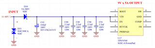
Please check this schematic that I'm starting:
I have few questions for now, later I can continue with another posts.
(1) INPUT VOLTAGE LIMIT - In a 48V automotive system, the input voltage can reach around 58V (14.5V on each battery when the forklift is operating). The TVS diode SMCJ60CA have as characteristics, "Voltage - Reverse Standoff (Typ)" of 60V, "Voltage - Breakdown (Min)" of 66.7V and "Voltage - Clamping (Max) @ Ipp" of 96.8V @ 15.5A. Both ICs TPS54560 and LM76005 have an Absulute Maximum Input Voltage of 65V. This is a doubt I always had and always wanted to ask about, what happens if in a very fast voltage surge event at the input, where the TVS diode clamps the voltage to a safer level, but it exceeds the maximum of 65V of the ICs for a very very short period of time? For some few micro-seconds? Does the ICs get damaged? I wonder if I will need to use for this project a buck converter that withstands even more higher voltage at the input.
(2) CAPACITORS - The electrolytic capacitor C92 I wanted to avoid it, the part number shown in the picture, EEV-FK2A331V of Panasonic, it is vibration-proof (suitable for our project), but it is a little expensive and also not easy to find. I did a research at Digikey website and concluded that if I need a 100V ceramic capacitor X7R or X5R with a reasonable price, it should be ceramic 2.2uF 100V 1206. 3.3uF or 4.7uF x 100V, even in 1206 or bigger packages, are too expensive. I could avoid the use of the 330uF electrolytic cap and use on its place many 2.2uF ceramic caps also. In the installation of the product, there will be the supply wires, that goes from the terminals of the battery of the forklift (+ and -) to the board, it will be used 2 wires in parallel for positive, and 2 wires in parallel for negative, in order to reduce the resistance and voltage drop, and will be used the thickest gauge wires that can be fitted to the metallic terminals of the housing that matches the PCB connector. The gauge of the wires and the length of the wires (it will be few meters) are not defined yet. We plan to use mini-FIT series for connector and housing, where the metallic terminals are bigger and should support thicker wires.
Correction: I searched again on Digikey about the 100V X5R or X7R ceramic caps, and it would be also ok to use some "CAP CER 4.7UF 100V X7R 1210" in parallel at the input, but the 2.2uF 100V are much easier to find and more available.
What can you say about this?
Suggestions are welcome.
Regards,
Jeferson.
