This thread has been locked.

If you have a related question, please click the "Ask a related question" button in the top right corner. The newly created question will be automatically linked to this question.

TPS628510: The SS/TR pin recommended and minimum voltage

Part Number: TPS628510

Hi Team

For the application using voltage tracking.

The datasheet mentions that a voltage ramp on SS/TR to 0.6 V ramps the output voltage according to the 0.6-V feedback voltage,

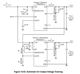
but for the example schematic in the datasheet, the voltage on the SS/TR pin of the device 2 is only 0.58V, and the current from SS/TR across R6 makes it slightly over 0.6V.

Does this mean that the voltage on SS/TR should be at least 0.58V to make it work? What would be the recommended and minimum voltage for this pin?

  • Hi David,

    Thanks for your question.

    In order to get a safe design, I would aim to get 0.6V on the SS/TR pin.

    It's true that there will be a small additional voltage drop caused by the pin leakage current to compensate for small mismatch, but the designer should aim to match as much as possible the feedback resistors divider.

    Please ask again if you have further questions.

    Thanks,

    Stefano

  • Hi Stefano 

    Much appreciate your answer! Adding some questions here.

    Is there a recommended value for the voltage on SS/TR pin?

    I think the design will be fine as long as the voltage on SS/TR pin is between 0.6V and Vin+0.3V(absolute max value), is this understanding correct?

    Regards

  • Hi David,

    What you are saying should be fine for the Absolute Maximum Ratings.

    But please consider that if you mismatch the resistor divider on the SS/TR pin with respect to the FB resistor divider, you would also mismatch the ramp up time of the output voltages (therefore you won't be anymore in a voltage tracking condition).

    Thanks,

    Stefano 

  • Hi Stefano

    Could you elaborate a bit about how the voltage on SS/TR affects the ramp up time of the Vout?

    Regards

  • Hi David,

    Please refer at section 9.4.7 of the device datasheet (TPS62851x 2.7-V to 6-V, 0.5-A / 1-A / 2-A Step-Down Converter in SOT583 Package datasheet (Rev. A) (ti.com)).

    The  internal soft-start circuitry controls the output voltage slope during start-up, proportionally to the external capacitor Css.

    When the device operates in voltage tracking (section 10.3.1):

    "The TPS62851x follows the voltage applied to the SS/TR pin. A voltage ramp on SS/TR to 0.6 V ramps the output voltage according to the 0.6-V feedback voltage. Tracking the 3.3 V of device 1, so that both rails reach their target voltage at the same time, requires a resistor divider on SS/TR of device 2 equal to the output voltage divider of device 1."

    This is why we should match the two resistor divider (on SS/TR of device 2 and FB divider of device 1).

    If this does not happen, the two output voltage won't have the same ramp time.

    Please ask again if you have further questions.

    Thanks,

    Stefano