Other Parts Discussed in Thread: TPS65218, , TPS6521815
i am attempting to reprogram the enable 2 register from 53h to 03h i am able to succesfully reprogram the eeprom however after power cycle, the register resets to 53h
This thread has been locked.
If you have a related question, please click the "Ask a related question" button in the top right corner. The newly created question will be automatically linked to this question.
i am attempting to reprogram the enable 2 register from 53h to 03h i am able to succesfully reprogram the eeprom however after power cycle, the register resets to 53h
Hi Joseph,
Thank You for posting this question on E2E! The ENABLE1/ENABLE2 registers are Read/Write capable but they are not backed by EEPROM. This means, all bits in those specific registers can be changed but the new values won't become the power-up defaults and data will be lost after a power cycle. Only bits with "E2" under the "Type Column" in the Register map can be re-programmed.
The good news is the enable registers are automatically loaded with data based on the SEQx registers. For example, if you want to make DCDC1 disable by default, then DC1_SEQ bit on register SEQ3 needs to be re-programmed to make the rail not controlled by the sequencer. Then you save it into the EEPROM and after the next power cycle, the enable bit that corresponds to DCDC1 will be 0b so DCDC1 will be disable.
Similarly, if you want to make DCDC1 enable by default, then DC1_SEQ bit on register SEQ3 needs to be re-programmed to assign a STROBE to the rail. After the next power cycle, since DCDC1 is now enable, the corresponding bit on the ENABLE register will be 1b.
Just to summarize: only the rails assigned to a STROBE in the sequencer will have a "1b" in the corresponding enable bit after a power cycle. Could you try making changes to the SEQ registers based on the rails that you want enable by default and the ones you want disable by default? Then, save those changes into the EEPROM and do a power cycle to see if the ENABLE1 and ENABLE2 registers reflect the changes. Let me know if this works!
Thanks,
Brenda
Hello Brenda,
thankyou for the clarification that you provided, the particular settings that i wish to change is in Enable2 bit 4 and 6. how can I control this. I Want all three GPIO's to not be HiZ.
Thanks,
Joe
Hi Joseph,
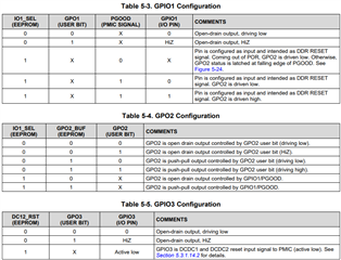
Which TPS65218 orderable part number are you using? If you are using TPS65218D0 specifically, then the following should describe the default configuration: GPIO1 should be open-drain output/driving low, GPIO2 should be push-pull output driving low and GPIO3 should be configured as input signal for DCDC1/DCDC2 reset. These are the default configuration for each of the three GPIOs in the TPS65218D0 variant. Those default settings can be re-programmed following the configuration table in the datasheet (see capture below) along with the GPIO1/GPIO3 bit on the SEQ7 register.
For example, if GPIO1 is configured as open-drain/driving low by default but it is assigned to a STROBE, then it will go high during power-up. If you want this signal to stay low, it can be done by writing "0b" to register SEQ7 (to disconnect GPIO1 from the sequencer), save the new value on the EEPROM and do a power cycle to confirm the new settings. Similarity, if you want GPIO3 to stay low, this can be done by changing the "DC12_RST" bit to 0b on the CONFIG2 register, save the new value on the EEPROM and do a power cycle to confirm the new setting.
Please try the recommendations above and let me know if they work!

Thanks,
Brenda
thanks for your reply, i'll try the settings you suggested.
I am using the TPS6521815 version of the part.
i set seq7 to 0x00h to remove both Gpio1 and 3 from the sequencing, this fixed my issue.