Dear members,
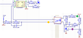
We used UCC28742 in our design and we faced to a question. We used TLP181 and LM4041 in the loop regulator. I will insert some photos to make the problem more understandable.
The probes are placed like in the following picture:
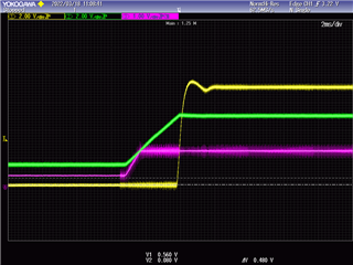
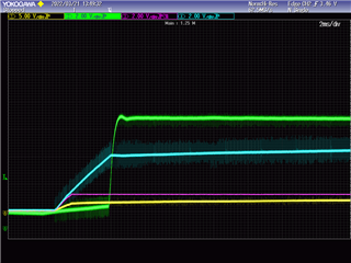
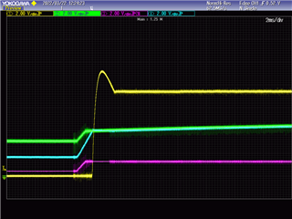
· YELLOW --> FB pin · GREEN --> Output Voltage · PURPLE --> Reference input
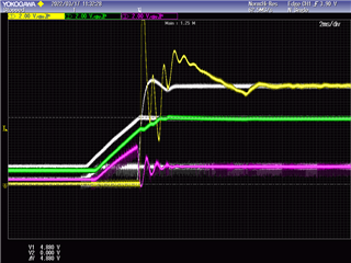
As you can see, the yellow probe shows that during almost 3ms at the start-up of the chip PS the FB seems to be grounded internally by the UCC28742. is it right? this behavior makes the output voltage goes up of 5V and it could be dangerous for the loads.
I appreciate it if any one can help me understanding why it's happening.