Hi,
we are using the TPS62625. The converter converts from 3.3V (+/-10%) down to1.2Vdc with an maximum output current of 280mA (lower in average).
Actually we are using an polymer tantalum capacitor as input capacitor (68uF, ESR=40mohm). Due to the size of the capacitor it is not as close as possible to the input pin and routing is done accross two layers so not optimal. We have directly at the input pin a ceramic capacitor component as it should be and it is placed as close as possible to the power input of the device. The capacity is limited due to component size.
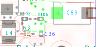
Refer to the PCB placement and layout extract:

C89 is the polymer tanatalum (68uF, 40mohm) and C36 is the ceramic capacitor, N3 is the TPS62625, L=1uH, Cout=68uF. The input power line is highlighted in green color.
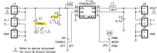
Question: What is the minimum capacity that the device requires in order to operate properly. Datasheet says 2uF. EVM-419 has a 4.7uF capacitor implemented. We can only get 1uF or even less capacitance with X7R material in 0402 size. Would this be sufficient, if we still have an additional bulk capacitor with 68uF (but placed not as close as possible to the pin)?
Attached there is a schematics from EVM-419 with modified values as reference:

We have done already tests without the ceramic capacitor at the input caused per accident and everything works but I guess the device may misbehave under certain conditons (e.g. large load transients).
Thanks in advance!
Best Regards,
Andreas N.


