Dear TI team,
I use the TPS61220 to boost a 3V battery to 5V, which works fine. In my application the TPS61220 is always in standby (enable pin 'low') and there is no load connected at Vout. I use a FET switch to isolate the load. TPS61220 is only activate when the auxiliary power (24VDC) is off, which will happen once a year maybe. When i measure the TPS61220 standby current (EN=0, Vin=3V, no load) i get values between 2,5uA and 3uA, which I am very happy with. Now i have a batch which draws 10uA to 12uA, roughly 15% of my ciruict boards failed during final test due to this high current. I double checked the design, but couldn't find anything. Circuit is an exact copy of the reference design. We also checked our production process for ESD or other type disturbance, nothing.
When i measure the standby current, I see that most of the current (6 to 9uA) is drawn by pin 5. Only a little goes to Vin. The 'good' TPS61220 doesnt show this behaviour.
My questions are:
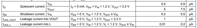
1 - What is the normal standby current when EN=0, Vin=3V and no load connected.
2 - Is it normal to have spread for standby current? normal values are 2,5uA, 15% (of 300 boards) are above 10uA
3 - We bought these booster IC from a distributor. Is it possible that we have parts which didn't go through quality checkor could be a copy?
4 - Any other suggestions?
Thanks in advance,
Yilmaz