Other Parts Discussed in Thread: ALLIGATOR
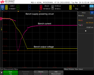
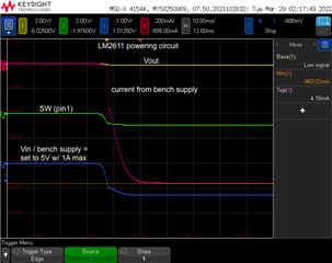
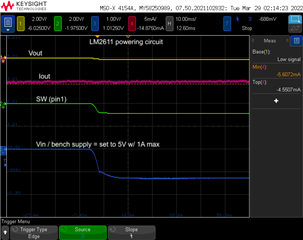
We have the following LM2611 circuit below that is powering a circuit that has a current consumption between 20mA and 80mA (verified by removing the LM2611 and using a bench supply). When we use a bench supply set to 5V and 1A max as Vin for the LM2611, the current limit is instantly hit. The circuit draws 1 A with the bench voltage sitting around 2 V (since the bench supply current limit is hit).

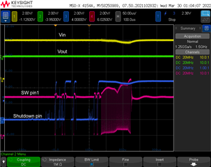
Below is from the LM2611 circuit when it is is disconnected from the circuit and instead has resistors loads.
Here are the 5V bench supply currents at different loads:
no load = 0.6mA.
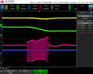
1kohm load = 22mA
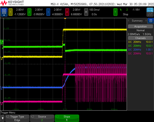
120 ohm load = 180mA
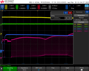
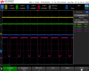
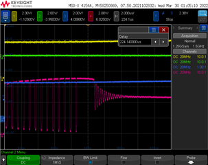
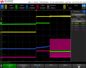
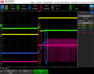
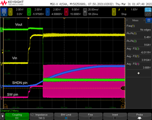
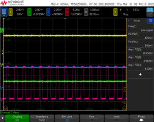
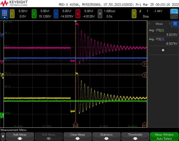
Below are scope captures under these load conditions.
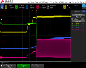
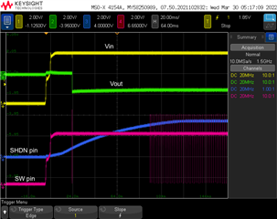
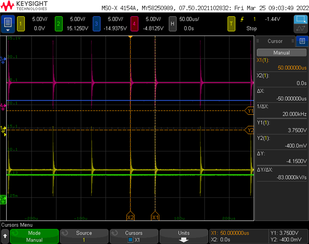
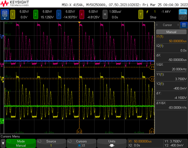
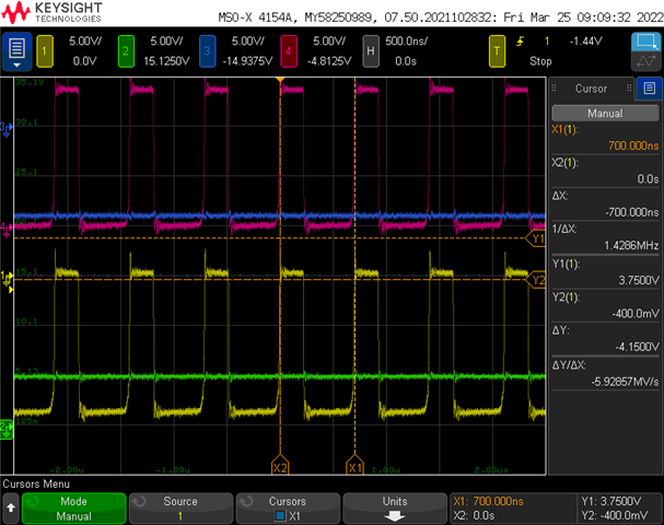
Ch1, yellow = D1 anode
Ch2, green = Vin
Ch3, blue = Vout
Ch4, red = pin 1 sw
No Load
No load, zoomed out
1k load
120ohm load
Also, this may be a side point, but the output voltage measures around 8.9 to 9V but the resistor divider should have this set to 8.65V
Can anyone provide some insight on why this circuit may draw excess amounts of current driving our circuit but appears to work ok with resistor loads? Is this a stability issue?