This thread has been locked.

If you have a related question, please click the "Ask a related question" button in the top right corner. The newly created question will be automatically linked to this question.

BQ25150: Issues with values of registers ICHG_CTRL and PCHRGCTRL 0x13 and 0x14

Part Number: BQ25150
Other Parts Discussed in Thread: BQ25155EVM, BQ25155

We are using BQ25150 in one of our boards

We are facing issue with the values of two registers in the IC

Content on reset as per the Datasheet
ICHG_CTRL (Address = 0x13) [reset = 0x8]
PCHRGCTRL (Address = 0x14) [reset = 0x2]

Content read on the IC over I2C on our board
ICHG_CTRL [reset = 0x00]
PCHRGCTRL [reset = 0x00]

We are not able to modify the content of these resisters either.

We are able to do read write on the following resisters in the IC.
BQ2515X_MASK1
BQ2515X_MASK2
BQ2515X_MASK3
BQ2515X_VBAT_CTRL
BQ2515X_TERMCTRL
BQ2515X_BUVLO
BQ2515X_CHARGERCTRL0
BQ2515X_CHARGERCTRL1
BQ2515X_ILIMCTRL
BQ2515X_LDOCTRL
BQ2515X_MRCTRL
BQ2515X_ICCTRL0
BQ2515X_ICCTRL1
BQ2515X_ICCTRL2
BQ2515X_ADCCTRL0
BQ2515X_ADCCTRL1
BQ2515X_ADC_COMP1_M
BQ2515X_ADC_COMP1_L
BQ2515X_ADC_COMP2_M
BQ2515X_ADC_COMP2_L
BQ2515X_ADC_COMP3_M
BQ2515X_ADC_COMP3_L
BQ2515X_ADC_READ_EN
BQ2515X_TS_FASTCHGCTRL
BQ2515X_TS_COLD
BQ2515X_TS_COOL
BQ2515X_TS_WARM
BQ2515X_TS_HOT

We have also tested our code with the BQ25155EVM kit.
There the registers are having expected reset value as per datasheet.

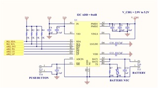
Please take a look at the circuit attached along.

Let us know what we are missing here.

  • Hi Vivek, 

    I reviewed your schematic, and it seems like the symbol is for the BQ25155 (C3 = NC). On the BQ25150 the C3 = IMAX and will determine the maximum fast charge current the device will support. You need to connect a 10k-ohm or lower resistor on that pin. 

    Both the BQ25155 and BQ25150 are firmware compatible, once the resistor is placed you should be able to change the charge current up to the IMAX setting. 

    Best regards, 

    Arelis G. Guerrero 

  • You are correct. The IC BQ25155 was to be placed here but was out of stock, so we put BQ25150. However forgot to put the resistor. The C3 is as shown by the Pink arrow, which now is difficult to put a resistor on. Is there some way we can charge the battery and try the prototype?

    Alternatively, we have to replace the battery each time it gets exhausted. 

    Regards

    Vivek Plawat

  • Hi Vivek, 

    It is difficult to tell with the picture and without looking at the pcb file, but it seems like the C3 (IMAX) is routed across the C4 (ADCIN) and I'm assuming connected to some GND plane/polygon. I'm not sure how much can you modified your board, but you could cut the trace from the ADCIN (C4) from GND and add a 10k resistor in there to GND. That will essentially have the C3 and C4 shorted, but that should be okay. This will allow you to test the prototype and you can change the layout for the next revision. 

    Best regards, 

    Arelis G. Guerrero