This thread has been locked.

If you have a related question, please click the "Ask a related question" button in the top right corner. The newly created question will be automatically linked to this question.

TPS546A24A: TPS546A24A EN Pin Voltage

Part Number: TPS546A24A

Hello TI Team,

I have a query related to EN pin of the TPS546A24A . I wan to enable the regulator through Hardware (EN Pin) with Voltage divider by using the values (R1233-10K and R1022- 6.04K). Voltage_En= 1.88V

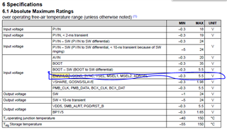
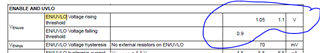
The Absolute maximum Ratings  for EN is given as -0.3 to 5.5V and Electrical characteristics is given as 1.05 to 1.1V. 


So Can some one suggest what voltage we can keep for EN pin to turn-on the regulator?

Regards

Kapil

  •  

    The Electrical Specification Table provides the voltage where the EN/UVLO pin transitions from Disable to Enable.  This is between 1.0V and 1.1V with a typical value of 1.05V, on the rising transition.

    The maximum allowable voltage on the EN/UVLO pin is 5.5V.

    With a 10k / 6.04k divider on the EN/UVLO pin, the TPS546A24A will attempt to turn on between 2.65V and 2.92V, with the internal 5μA current providing an extra 50mV of hysteresis on top of the 185mV of hysteresis from the EN/UVLO pin's 70mV internal voltage hysteresis.

    However, with AVIN powered by the PVIN input, and VDD5 not externally powered by a separate source, conversion will not be enabled until AVIN and VDD5 rise above 4.0V, so the EN/UVLO pin will not be providing a UVLO function.

    I also noticed that your schematic shows a 10Ω resistor from PVIN to AVIN.  For a 5V input, I would recommend a smaller resistor and larger capacitor to achieve the recommended 10μs time constant in order to reduce the drop across the resistor.  I can not see your switching frequency, but the AVIN current during operation is approximately 10mA + 5mA for every 100kHz of switching frequency.  (35mA at 500kHz) which can lead to significant voltage drop across the PVIN to AVIN resistor.

    In addition, for 5V inputs that will not exceed 5.5V, the 5V input can also be provided to VDD5, eliminating the LDO drop-out from AVIN to VDD5 and improving gate drive current and efficiency.

  • Hello Peter,

    Thanks for the clarification. So what is your suggestion for EN pin voltage divider? I see in the WEBENCH® POWER DESIGNER  the values are 13.3K and 3.83K. Should I go with this value?

    For 10E resistor It is showing  the same time the value in webench. So should be follow the web-bench design?

    For the switching frequency we are going with 450KHz. 

    Sharing the design for your reference (Vin-5V and o/p is 3.3V@1.5A.)

    Regards

    Kapil

  •  

    The resistors should be sized based on your desired level of hysteresis and minimum PVIN voltage that will guarantee turn-on. 

    To set the PVIN voltage that will guarantee turn-on, size the resistor divider to provide 1.05V at the lowest VIN that will guarantee turn-on.  For 3.83kΩ and 13.3kΩ, the TPS546A24A might not turn on until VIN reaches 4.7V  If that is acceptable, those resistor values are fine.  

    To se the absolute resistances, consider the turn-off.  The TPS546A24A will source 5μA of current and lower the threshold voltage 70mV.  The 70mV pin threshold change will provide 328mV of hysteresis, while the 5μA current source will provide 66mV of hysteresis for a total of 394mV.  If you want more hysteresis, increase the value of both resistors proportionally to increase the hysteresis.

    For the PVIN to AVIN resistor, with a 5V input at 450kHz switching frequency, there will likely be 250-300mV of drop across the resistor, which will limit the gate drive voltage.  It will work, and since this is a sub-10A application, the efficiency impacts of the lower gate drive voltage are likely not critical.  However, I would generally recommend a 2.2Ω resistor and 4.7μF capacitor for 5V input recommendations.

  • Hello Peter,

    Thanks for the clarification.

    For 1.05 we are talking about typical values, Now it depends on resistor tolerance as well. So I think I should make the voltage divider for 1.1V. What is your suggestion on this?

    It means For 3.83kΩ and 13.3kΩ, the TPS546A24A might not turn on until VIN reaches 4.7V(It's something like it under voltage protected until it is crossing 4.7V right?).

    What about 12V input and Regulator EN control from MPU/FPGA? 

    Do I also tune the 10ohm resistor for such case? What will happen for Vdd5 pin as well?

    Regards

    Kapil

  •  

    I had been using 1.1V in my calculation, which is why I also came up with 4.7V.

    Until the EN/UVLO is above it's threshold voltage, the output of the TPS546A24A will remain off and the converter in "Under Voltage Lockout"

    To Add MPU/FPGA control of the EN/UVLO, you can add an open-drain pull-down to the EN/UVLO level to force the EN//UVLO pin below its threshold , and then release it to follow the resistor divider, providing a combination of both Enable and UVLO functions on the same pin.

    Unless externally powered, VDD5 will track the lower of 50-100mV below AVIN or 4.7V.