Other Parts Discussed in Thread: TCA9554A
No one on our small team has little to no experience with motor/solenoid control layout, so we are looking for some suggestions/examples on best way to layout our DRV104-based board.
Our design requires control of two separate solenoids that control locking mechanisms. Each is controlled by a small board with a single DRV104 on it. These solenoids pull 600ma before the DRV104 starts to pwm @ 60KHz and the current drops to 200ma. The design has a single cable that brings 12VDC, Ground, I2C clock, and I2C data to each board. The I2C bus goes to a GPIO port expansion device (TI TCA9554A) to control/monitor the DRV104. We have shielded cables on all the lines, but still see more noise in the system that we would like when the PWM kicks in.
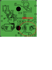
The DRV104 does not give any suggestions for layout/design other than the PCB footprint. Our layout guy currently has the top layer as signals with a ground pour (I have attached a screenshot of the gerber), the second layer is split between a 3.3V and 12v plane and the third/fourth layer are ground planes (which seems to be overkill).
Does anyone have an example layout or suggestions for a DRV104?
It seems with proper layout that this could be done in a two layer board? Correct?