This thread has been locked.

If you have a related question, please click the "Ask a related question" button in the top right corner. The newly created question will be automatically linked to this question.

TPS7A47: TPS7A4700 +34V to +33V Regulation ?

Part Number: TPS7A47

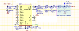
I have a TPS7A4701RGW in my design and I would like to supply it with +33.9V and get it to regulate my output voltage down to 32.9V. I have calculated the required resistors as R1 = 36K & R2 = 1.6K and have implemented this design. However I get a Vout = 33.52V ? I can change the input supply a little if need be ! I need Vout to be at least 32V ! 

Is there anyone who can help me with this ?

  • Hi Shmuel,

    Is it possible to share LDO schematic? It would help me to troubleshoot.

    The resistor sizes you chose are good. What are the tolerances for the resistors? 1%?

    What is the load current for this application? Are you measuring VOUT at room temperature? 

    As far as I can tell this device can support this configuration. Note, however, that with a high VOUT like this, the 1% output accuracy spec (at 25C TJ) of the device becomes a wider range (1% of 32.9V = 329mV), and with additional errors from the feedback resistors this can become even greater. 

    Regards,

    Nick

  • Dear Nick,

    Thank you so much for your quick response. Please see below the schematic below :-

    Yes we are using 1% resistors ! 

    Currently the Max load current is 15mA ! 

    Yes I was testing at room temperature !

    Thank you for pointing out the 1% output accuracy giving 32.9 + 0.329 = 33.229V. Do you think that the remaining 0.291V error could be from the "additional errors from the feedback resistors" ?

    The Vout=33.52V we could deal with, I just have to make sure that this is not a fault in the design and that we could rely on the TPS7A4701RGW for such a configuration for our customer !

    We could change the input supply and also Vout as long as we keep Vout> 32V ! Would you suggest a different configuration ?

    Bests regards

    Shmuel

  • Hi Schmuel,

    Your schematic looks good. 

    With 1% resistors the worst-case error is when the top resistor is 1% high and the bottom resistor is 1% low (1.01/0.99 ~ 2% error), and this is probably where most of your error is coming from. Try using 0.5% or 0.1% resistors and the error from the resistors should be much less. The accuracy spec for the device itself will guarantee that your VOUT will be greater than 32V, so long as other sources of errors are not dominating the total error. 

    Regards,

    Nick