This thread has been locked.

If you have a related question, please click the "Ask a related question" button in the top right corner. The newly created question will be automatically linked to this question.

BQ2970: Does not recover from under voltage protection (UVP) on charger

Part Number: BQ2970
Other Parts Discussed in Thread: BQ25101

Hello,

We are currently using the BQ29707DSER in our design and are having trouble recovering from device under voltage with the charger. I believe we've verified that the BQ29707 can reset as I've injected 4V across PACK+ and PACK- and seen the device recover from there. After that test, I've gone to see if the charger is giving us a problem. We are using the BQ25101 charging chip. Are these two chips known to work together? We are able to get the battery to charge but are unable to recover from the fault condition. I've seen that upon connecting the battery with battery protection in UVP fault state, the voltage of the BQ25101 output drops to ~.8V. Upon investigation I realized the battery protection chip is pulling V- to BAT effectively shorting PACK+ and PACK- and I believe we are seeing the BQ25101 detect a short and shutting off the charging capability thus preventing the BQ29707 from releasing UVP.

Please advise to what we should do. I can add schematics/test data if necessary, thanks.

  • Hi Anthony,

    Are you able to share the test data and any plots you have?

    Also does the protector you have contain the 0V inhibit feature?

    Regards,

    Gautham

  • From the BQ29707 datasheet, I believe the 0V charging inhibit function is present. However, in our case we are using the device to control a stepper motor which causes the battery voltage to dip and decrease over time. If the voltage is low and the motor is running, the voltage may dip below 2.8V causing the device under voltage fault to occur. Once this happens, the motor stops running and the battery returns to an acceptable voltage up to 3.6V depending on how long we ran the motor. We are not trying to charge a low voltage battery.

  • Is there any specific signals you are particularly interested in? I only have a 2 channel scope available so will need to take multiple snapshots and choose sparingly

  • Here is a capture of the stepper motor running til UVP is reached. The Yellow signal shows the voltage across BATT-(VSS) and BATT+(BAT).  Refer to my previous comment where the battery returns to the acceptable voltage after dropping below 2.80V. The blue signal shows the voltage from BATT-(VSS) to GND(VSS) showing that once UVP is reached, the fault occurs where BQ29707 pulls V- to BAT. 

    This is the first screenshot with some rough voltage measurements of where the fault occurs and the battery voltage after the fault.

    This is a capture of the voltage seen at the output of BQ25101. It is first trying to detect a battery at the beginning and then when the battery is detected, drops voltage down to 600mV

  • Hi Anthony,

    The plots help. Post when the battery detect is run, with the voltage dropping to 0V(from BQ2510x VBAT with reference to BQ2510x GND), do you still see current from the charger IC? It should be around 11mA which is the IOUTSC parameter. During this time- have you tried disconnecting the load to see if the BAT voltage will rise?

    I need to check if the protector behavior is as expected. 

    Regards,

    Gautham

  • I'm seeing ~11.89mA at OUT. I haven't tried disconnecting the load as the battery protection circuitry and load are connected through our custom PCB

  • Is it required to disconnect the load for this charger/protection chip combination to work? 

  • Hi Anthony,

    The load may be pulling current so it’d be good to see if the load is pulling the voltage of the battery down.

    If it recovers without the load, then we know there isn’t enough current going in to the protector to close the connection to the battery

    Thanks,

    Jackson

  • Jackson, Gautham I am going to try and figure out how to disconnect the load with our PCBA, but once I've disconnected the load is there a minimum current/voltage that will release the over discharge state?

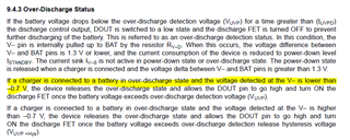
    Also, going through the datasheet, can you provide clarification of the -0.7V seen at V- to release the over discharge state? What is the ground reference for this voltage? I've included the screenshot of this part of the datasheet.

    Thanks.