This thread has been locked.

If you have a related question, please click the "Ask a related question" button in the top right corner. The newly created question will be automatically linked to this question.

UC1843A-SP: Feed-forward compensation application

Part Number: UC1843A-SP
Other Parts Discussed in Thread: UC1843A,

Hi,

I'm trying to find some formula and technical notes about how to design feed-forward compensation network for my dc-dc application.

Please provide me some technical note to do it with uc1843a.

I know that the input voltage variation will be associated to FB pin. However, I need further calculations for that network.

I also have closed loop feedback circuit that is connected to the FB pin in addition to feed-forward compensation

  • Hello Gg,

    The controller works with current mode quite well which accomplishes the benefits of feedforward compensation without dealing with voltage mode.
    Our online calculator can help calculate the needed components for you for a flyback converter.

    https://www.ti.com/product/UC1843B-SP

    I am unable to provide an app note to of compensate it with feedforward voltage mode compensation

    Thanks,
    Daniel

  • Hi Daniel,

    The controller can perform pulse-by-pulse current limiting. However, if input voltage varies between 20V to 40V considering flyback, the allowed output power also increases. Because we design the current sense resistor considering 20V. However, if input voltage varies to 40V the allowed input power can go up because resistor is fixed.

    The pulse by pulse current limiting doesn't benefit for this feed forward issue. We need to inject the input voltage variation information to the current sense or feedback pin. I need some guideness.

  • Hey Gg,

    The output power does change with input voltage as the slope of the current changes with input voltage.
    Since you are looking at the peak current, there is a different duty cycle and peak current at each different input voltage.


    One of the big draws to current mode over voltage mode is that current mode is robust to changes in input voltage.
    Feedforward voltage mode tries to fix this problem, but this problem is already fixed with current mode.
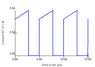
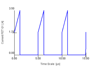
    This is the same converter with different input voltages.
    See how the peak current changes:

    Thanks,
    Daniel

  • Hi Daniel,

    Thank you for your effort.

    Just considering below case;

    Vin:20-40V Vout=5V Iout=3A , so I set Rcs for 20V input and 15W output power

    However, if Vin=40V Iout can be 3.5A that measn 17.5W output power.

    I still need feed forward compensation to limit output power to 15W when Vin =40V.

    Please, see figure 25 of uc1843a-sp datasheet. There is resistor network from Vcc to Vfb. The Vcc is from Vin therefore, the feedforward achieved in some way. Maybe this figure with some calculations help me. Could you please help me?

  • Hello gG,

    One last thing before I can fully help with calculations is your transformer specifications (Turns ratio and inductance) and what frequency you are running at.
    This will allow me to help with calculations.

    Note that I will be using power stage designer which is available on our website for free use.

    Thanks,
    Daniel

  • Hello Daniel,

    Turns ratio= 2.87/1 (npri/nsec)

    Lmag=40uh

    fsw=300khz

    dmax=0.45

    I also used power stage designer tool.

    Thanks in advance.

  • Hey gG,

    If you are using power stage designer you can see the peak currents yourself by clicking on the Q1 in the diagram.
    Also of note is that if you are using CCM the power transfer is done by the equation:
    (0.5*L*IMAX^2 - 0.5*L*IMIN^2)*f

    Looking at the values from power stage designer you can see that input power is 17.1 W no matter the input voltage.
    Power stage designer puts it in calculated values.
    When you size your resistor you should be sizing it much lower than what it would take to trip the over current protection of your controller.

    Thanks,
    Daniel