This thread has been locked.

If you have a related question, please click the "Ask a related question" button in the top right corner. The newly created question will be automatically linked to this question.

CSD19538Q3A: How to find Rds(on) in specific application

Part Number: CSD19538Q3A
Other Parts Discussed in Thread: TPS23880

Hi,

I would like to have some help about the CSD19538Q3A. 

My application is the folowing : 

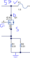
When transistor is ON, it closes a circuit and a current of 1.25 A is flowing through the transistor. The gate is controlled from 10 V to 12.5 V. 

When transistor is OFF, it opens the circuit and there is no current flowing. 

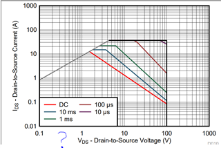
To check if the transistor as an enough SOA, I need to know the exact value of Vds. How to know it ?

I though to use Rds (on) to calculate Vds (because used in ohmic region)  : Vds = Rds (on) = Ids 

Rds (on) is given figure 7 page 5 but for a Ids = 5A.

Thank you for your help 

Pierre

  • Hello Pierre,

    Thanks for your interest in TI FETs. Can you share additional information about your application? Are you using the current sense resistors in the source leg of the FET in a feedback loop to regulate the current through it by adjusting VGS? Or, are you just turning the FET on (VGS >> Vth) and the current is regulated elsewhere in the circuit? If you're using it like a pass element in the saturation region (where Vds > Vgs - Vth), then we have to be concerned about the voltage drop across the FET when there is current flowing thru it to make sure it's operating within the SOA limits. If you're using the FET as a switch, then we need to know the turn on and turn off times to determine if it's within SOA. I look forward to your response.

    Best Regards,

    John Wallace

    TI FET Applications

  • Hello Pierre,

    Following up to see if your issue has been resolved. If I do not hear back from you, I will assume it has been resolved and close this thread.

    Best Regards,

    John

  • Hi John,

    Thank you for your complete reply. I'm on internship and available at the company 3 days from monday to wednesday per week.

    I'm working on different topics, I will answer to your questions as soon as possible.

    Regards,

    Pierre 

  • I will use this MOSFET or another one for PoE application, especially the TPS23880. I know the CSD19538QA is recommended on the evaluation kit but I would like to understand how it was chosen to have some references. 

    If I understood the behaviour of the TPS, the current is measured in the TPS through a resistor. Then the TPS will drives the gate to ensure a good behaviour for functionnalities. 

    I understood that the maximum current through the MOSFET is 1.25 A  like described on page 31 of https://www.ti.com/lit/ds/symlink/tps23880.pdf?ts=1649669262878&ref_url=https%253A%252F%252Fwww.ti.com%252Fproduct%252FTPS23880

    This maximum current is when the gate is driving the MOSFET high (Vg = 10 to 12.5 V) so Vds will be very small and goes to 0V. To chose the MOSFET ans regarding to the SOA surve, I need VDS at 1.25 A. 

    Tell me If i'm not clear.

    Regards 

    Pierre

  • Hi Pierre,

    I was not involved with the TPS23880 EVM design but I believe the CSD19538Q3A was chosen because it is 100V FET in a small, 3.3x3.3mm package and can handle the current requirements of a PoE application. For SOA, we need to look at the turn-on and turn-off times of the FET. If you are switching 54V in 100μs, then the SOA current is about 5A. We also need to consider the continuous current and conduction loss in the FET when it is ON. For 10V, gate drive the maximum on resistance is 59mΩ and the conduction loss for 1.25A continuous is: Pcond = 1.25A x 1.25A x 59mΩ x 1.7 (assuming TJ = 100°C, see Figure 8 in the datasheet) = 157mW. This is well within the capabilities of this package. I am going to pass this inquiry over to the TPS23880 apps to add their inputs.

    Thanks,

    John