Dear Sir:
The card was manufactured and soldered already, but the chips of tpsm63606 are very hot after several minutes? I have used 3 pcs tpsm63606, is it too much?
This thread has been locked.
If you have a related question, please click the "Ask a related question" button in the top right corner. The newly created question will be automatically linked to this question.
Dear Sir:
The card was manufactured and soldered already, but the chips of tpsm63606 are very hot after several minutes? I have used 3 pcs tpsm63606, is it too much?
HI
can you help decrbied the input and output condition? what's the frequency you set, whether its output is normal?
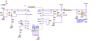
20V input, output1 12V, output2 15V, output3 -15V, RT=13Kohm, the frequency should be 1MHz, the output value is correct as designed. Please refer the schematic as attached.
I do not know I always failed to upload the pdf file, so I upload the picture twice, sorry

HI yuliang:
no problem, all the 3 rails are all hot or only negative output module is hot? what is the load condition?
Hi Daniel:
The negative is very hot, 12V is hot , 15V is also hot. Now, I didn't connect any load.
HI
Can you try to increase the frequency of -15V to 2.1Mhz? and see any improve, one more assumption is for the ripple current of inductor in the module is large which make the module hot in no load condition.
Thanks
Yes, I replace the RT with 6.2Kohm. After this, only -15V output was very hot. Is there anything wrong with the design of the -15V output ? Can you help to check it? Any comments?
Hi for -15V,
you need to set the frequency between 1.8-2.2Mhz, and cause the actual mosfet voltage rating is input + output, so it is around 35V , the max output current is around 3A. the mosfet is very close to its max voltage, so I think it is the reason for module is hot, and by the way, do you give the module enough copper for thermal dissipation?

RT is replaced with 6.2Kohm resistor and the heat is still there. This afternoon, I just enabled -15V output, When Input is 19V, it is still very hot. It is obvious that -15V generate the heat. I changed the input to 15V, 12V,10V, the output is still -15V. But when I changed the input to 9V, it didn't output -15V, only 600mV. Anything is wrong?, the schematic is attached, please check it. Is there any error in the schematic?Powercard V301.pdf
HI yuliang:
I did some wenbench estimation, it looks in very light load, the silicon still have 1.14W, I think it is due the inductor and switching loss in high input voltage.

pls notice this condition is 35Vin 15Vo Io=0.1A buck , the inner mosfet and inductor will have same voltage and current stress as 20Vin -15Vo 0.05A inverting buck boost condition