This thread has been locked.

If you have a related question, please click the "Ask a related question" button in the top right corner. The newly created question will be automatically linked to this question.

TPS65217CEVM: Power Lockup with OSD3855

Part Number: TPS65217CEVM
I use an Octavo Systems module (pn: OSD3855) which contains the TPS65217C.  There is a known problem where the pmic (TPS65217C) will "lockup" during a brown out as noted in TI app note SLVA901 ((https://www.ti.com/lit/an/slva901/slva901.pdf?ts=1649341520346&ref_url=https%253A%252F%252Fwww.google.com%252F).  I implement the suggested solution by TI in the app note (i.e. "Solution Circuit Number 2 for Case A (No Battery)"; Figure 7 in document SLVA901).  When the solution is implement the TPS65217C does not lockup.  However when I intentionally tried to induce the lockup by restoring "AC" (i.e. 5V) in less than 1 second per Figure 9 in document SLVA901, the TPS65217C did not lock up.  Is the 1 sec window to restore "AC" fixed or is there a tolerance?
  • Hi Nai,

    Thanks for reaching out! We will look into this functionality and provide an update within the next 2 business days.

    Thanks,

    James

  • Hi Nai,

    It looks like this issue is being discussed on another E2E thread located here: Power Startup Issue on Nova Control Module

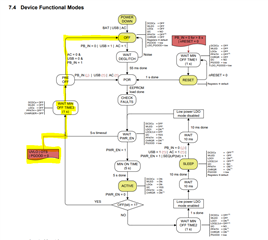
    The 1 second timer is just a minimum wait time before the device decides which state to proceed to next. If VIN_AC is restored by the time the PRE-OFF state is reached, the device can move to the "power on reset" stage without moving to the OFF state. However, a fault check must still be passed in both cases (VIN_AC stabilized before OR after the 1 second timer). The difference between the two cases (once brownout is solved and no longer causing lockout), is the WAIT DEGLICH stem between the OFF state and the POR step.

    Regards,

    James

  • Hello James, 

    Thanks for the feedback.  I had thought it was the restoration of VIN_AC before the 1 sec which was the cause of the lockout, but it appears I conflated the lockup behavior with the 1 sec timer. 

    Per my review of the TPS65217C datasheet, in Table 37 it states "In an application with one source of input power, if the input power drops below UVLO and recovers before reaching 100 mV, the rising edge may not be detected by the device". In my case the one source of input power is VIN_AC.

    As I noted in the first message, after implementing  "Solution Circuit Number 2 for Case A (No Battery)" in Figure 7 in TI document SLVA901, I intentionally restored VIN_AC before it reached 100mV, and I could not induce the lockout. 

    1) What is the mechanism/cause of a brownout lockup?  

    2) How does implementing the 1k pull down from VBAT to gnd as specified in the  "Solution Circuit Number 2 for Case A (No Battery)" help with preventing the lockup? 

    3) What influence does VBAT have to the lockup behavior?

    Though the solution specified clearly works, I'm seeking a better understanding of the lockup behavior in case there is a corner use case which the solution may not resolve.

    Thanks,

    Nai

  • Hello Nai,

    We should be able to respond to your latest post by tomorrow at the latest. Thank you.

    Regards,

    Alex

  • Hi Nai,

    1) The lockup itself is related to the 1-second fault timer from the picture in my last reply. When the VIN_AC voltage falls below the UVLO threshold, the fault timer waits 1 second while the LDOs / Load Switches and DC-DC converters are shut down. During this time, the power path of VSYS is still connected to the BAT pin. Normally, the device enters a pre-OFF state after the 1-second timer and if the VIN_AC voltage rises above UVLO after this timer is finished, the recovery will be detected properly and the device will move to the "power on reset" sub-state (POR in the picture). 

    However, if the VIN_AC recovers too quickly, the recovery rising edge of the input will occur before the 1-second fault timer is over and the VIN_AC recovery will not be detected properly. A normal battery would take over the input voltage and allow the 1-second fault timer to expire in this case and the device would reboot as expected. The lockup occurs because the "battery" in Case A is just a small voltage stuck on the passive capacitor that does not meet the UVLO threshold. Thus, the device misses its VIN_AC detection and then gets stuck in a fault loop while looking at the low BAT voltage.

    2) The 1k pull-down allows VSYS and VBAT to fully discharge which ensures that the fault detection does not get hung up on a fake battery voltage after the 1-second timer. This isn't an issue if VIN_AC recovers after the 1-second timer because the VIN_AC signal provides the input to stop the fault loop and move to a new sub-state. The issue with VBAT occurs if the VIN_AC recovery time is faster than the 1-second timer.

    3) The VBAT influence is only related to the fault detection. The resistor is used to make sure that VBAT, and by extension VSYS, are discharged enough to allow the fault detection to run its course.

    Thanks,

    James