Dear TI,
I am designing an electronic access control system which must provide power to peripherals at 12VDC and, in some cases, 24VDC, with total output current from 0 to 3A. The system is powered from a 32V AC/DC PSU with battery backup. The battery is lead acid and will either be 12V rated (approximately 14V when fully charged) or, if 24VDC outputs are required, the battery will be 24V rated (approximately 28V when fully charged). Therefore, to create the regulated outputs, I need a DC/DC converter which provides 0 to 3A at either 12V or 24V (user selectable) from an input voltage ranging from 32V down to 25V (12V or 24V output) or down to 12.5V (12V output only).
When the battery is depleted, the input voltage may fall to 12V (or 24V) or even a little lower, in which case the DC/DC converter will be operating in drop out. It is acceptable for the output voltage to reduce a little in this situation, so long as the regulator remains stable. I realise that I could maintain regulation using a buck-boost converter, but I do not feel that the added complexity is worth it - best effort using a buck converter feels appropriate in this case.
I have chosen the LMR33630ADDA because it seems to meet the requirements and the data sheet specifies a low drop out voltage. Working through the design guide, I have selected a 22uH inductor (Pulse PA4343.223NLT) which has DCR 33 mOhm. I am using a hybrid polymer aluminium electrolytic output capacitor of 100uF with max ESR 22mOhm.
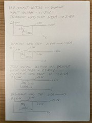
I prototyped this design using the LMR33630ADDAEVM (I replaced the inductor and output cap) and it seems to work well, even when operating in drop out. The transient response to large changes in load shows a modest deviation in output voltage (around 7%). The response is a little underdamped - I see a trough followed by a peak, but I see no further oscillation beyond that.
The reason for my question is that I used Webench to simulate the design and this indicated a problem. If I configure Webench to use a low input voltage, such that the regulator is in dropout, then the bode plot shows it to be unstable. Is this because the Webench model is not valid when the device is operating in drop out, or does this indicate that there may be a problem with my design?
Thanks for your help.
Best regards,
Gavin.


