Other Parts Discussed in Thread: TPS27S100, TPS1H100-Q1
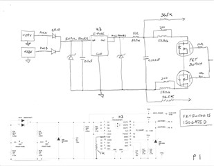
Image 1
I am using an E-Fuse (TPS16630PWPT) in a new project, and encountering some unexpected behavior.
I am turning an external resistive load on and off with a isolated solid state switch consisting of two FETs.
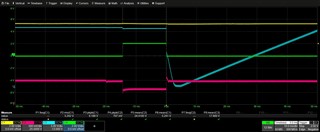
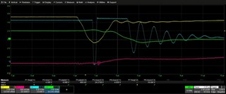
Image 2 and 3.
Turn on is OK, but when the current is switched off, the E-Fuse does not remain on as expected.
Instead, the E-Fuse fault line becomes active for about 2us. Then the E-Fuse switches off with the output dropping to 0V for approximately 200ns.
Afterwards, the E-Fuse recovers and stays on for about 3us before the output starts to ring and eventually drops back down to 0V and begins a new dv/dt start up cycle.
It looks like the wiring inductance in the test setup is affecting the E-Fuse in a negative way. Is the E-Fuse meant strictly to be used to power circuits on a PCB only?
Image 1 is a section of my schematic diagram and shows how the E-Fuse is configured.
There is also a schematic showing the resistive load connected to the output of the E-Fuse and the FET switch.
There is approximately 8-10ft of wire connecting the entire circuit loop.
a. Input voltage range is 20V – 40V. Nominal is 28V.
b. Current limit is set for 3.6A
c. Startup dv/dt is 41.6ms - 83.2ms. Nominal is 58.2ms.
d. No Auto retry
e. Load resistance is 11 ohms
f. 0.022uf load capacitance
Image 2 shows four scope traces
a. Yellow is E-Fuse fault line
b. Blue is E-Fuse output voltage
c. Green is load current 2A
d. Red is E-Fuse input voltage
Image 3 shows the same scope traces expanded at the point where current is interrupted and shuts off
a. Yellow is E-Fuse fault line
b. Blue is E-Fuse output voltage
c. Green is load current 2A
d. Red is E-Fuse input voltage