Because of the Thanksgiving holiday in the U.S., TI E2E™ design support forum responses may be delayed from November 25 through December 2. Thank you for your patience.

This thread has been locked.

If you have a related question, please click the "Ask a related question" button in the top right corner. The newly created question will be automatically linked to this question.

LM66100-Q1: Please help to check schematic

Part Number: LM66100-Q1
Other Parts Discussed in Thread: LM66100, TPS2116

Hello Sir:

We want to use LM66100-Q1 on battery pack protection.

Our function requirements shows below.

1. only discharging from battery side to load side.

2. cannot charge battery in any time.

3. detail voltage operation range is 2.0~3.6V

4. discharge current is 200mA (peak)

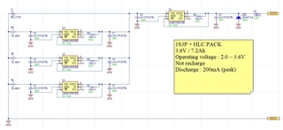
Would you please help to check below schematic and let us know which will meet our requirements?

Looking forward your feedback.

Thanks a lot.  
  • Hello Statham,

    I apologize for the delay, but I will have a response for you by EOD 4/19/22. Thanks for your patience!

    Regards,

    Kalin Burnside

  • Hello Statham,

    The LM66100 device requires a 35mV drop from Vout to Vin to enable RCB which can mean up to 500mA of reverse current. With variance between batteries and devices some will be at higher/lower Ron and therefore some rails will inherently be at a lower potential causing some amount of reverse current. Load sharing like this is not recommended.

    It might be possible to use power MUX devices that select the highest voltage to send to the output but this will require some sort of cascaded topology of multiple powerMUXes. I would suggest looking at TPS2116.

    Regards,

    Kalin Burnside