This thread has been locked.

If you have a related question, please click the "Ask a related question" button in the top right corner. The newly created question will be automatically linked to this question.

LM5156-Q1: application question

Part Number: LM5156-Q1
Other Parts Discussed in Thread: LM34966-Q1, UCC28C41-Q1, LM5156

Dear team,

My customer plans to use our device as flyback controller(Primary-Side Regulated).

1. Our device doesn't have SCP/short circuit protection, do we have any solution to achieve this function? For example, the output load is shorted. 

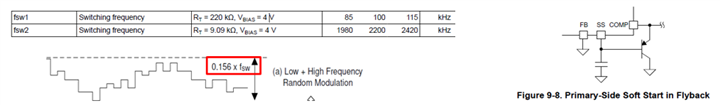
2. Compared with LM5156-Q1, LM34966-Q1 doesn't include the spread spectrum function. My customer is sensitive to the cost, so they also evaluate our LM34966-Q1. They want to know whether we can add external circuit at RT pin to achieve the spread spectrum function for our LM34966-Q1.

3. Our LM5156-Q1 use internal transconductance error amplifier, and some devices use normal amplifier, for example, UCC28C41-Q1. Could you please tell me why we use transconductance error amplifier instead of the normal one?

Thanks & Best Regards,

Sherry

  • Hi Sherry,

    Thank  you for posting.  Below are my answers to your questions.

    1. The IC has over current protection in hiccup mode, which can be used to cope with the flyback output load short condition.

    2. If they want the spread spectrum function, please use the LM5156 instead.  Adding and external circuit at RT may work but it may cost more.  If the want take this approach, they should apply a triangular voltage through a resistor to the RT pin to achieve the spread spectrum function.  Note that the instantaneous frequency follows the datasheet equation in which the RT resistor now needs to be replaced by the equivalent resistor seen by the RT pin.   

    3. One advantage is the FB pin of the LM5156 can also be used for output overvoltage detection, therefore we can achieve output OVP function without additional external devices. 

    Thanks,

    Youhao

  • Hi Youhao,

    Thanks for your reply!

    The IC has over current protection in hiccup mode, which can be used to cope with the flyback output load short condition.

    The IC will enter hi-cup mode after the cycle-by-cycle current limiting occurs 64 times, its an overload protection, too slow to protect the devices during output load short condition. Any suggestion to turn off the MOS in several cycles after output load short condition happens?

    One advantage is the FB pin of the LM5156 can also be used for output overvoltage detection, therefore we can achieve output OVP function without additional external devices. 

    The normal OPA also can achieve the OVP function through FB pin, it seems not the difference or advantage with the OPA.

    In addition, my customer is interested in our Dual Random Spread Spectrum, and we have one document to introduce this(https://www.ti.com/lit/an/snva974/snva974.pdf?ts=1649932247315&ref_url=https%253A%252F%252Fwww.ti.com%252Fproduct%252FLM5156-Q1%253FkeyMatch%253DLM5156-Q1%2526tisearch%253Dsearch-everything%2526usecase%253DGPN). But it is a general description. They want to know whether provide more detailed about the circuit or theory how to achieve the DRSS mode. 

    Thanks & Best Regards,

    Sherry

  • Hi Sherry,

    64 cycles is not too long.  If you switch at 400kHz, 64cycles is just 160us delay.  Note that during these 64 cycles the peak current limit is in action and the duty cycle would be cut to small.  Such protection has been used by other customers.

    If you use OPA, the FB pin voltage is no longer a fixed ratio of the real time output voltage, because there would be current through the compensation network from the COMP to the FB during dynamic operation. 

    The DRSS just combines different types spread spectrum schemes to take the advantages of each of them.  But the fundamental concept is the same.  There are lot info in the literature which you can search online.  Here is one of them:

    https://www.ti.com/lit/pdf/slyy208?keyMatch=EMI

    You can jump to the Spread Spectrum section. 

    Thanks,

    Youhao

  • Hi Youhao,

    Thanks for your reply!

    Could you please help answer below questions?

    1. Whats the accuracy of fsw when disable the DRSS? In below picture, for max fsw, the accuracy is 10%, and for the minimum fsw, the accuracy is 15%. Then what is the accuracy when fsw is between max. and minimum?

    2. And whats the range of fsw when enable the DRSS?

    3.In figure 9-8, why use a transistor to connect COMP and SS? Without the transistor, we can change the soft start time also. And why connect the FB to the GND?

    4. In page 16,The RT pin is regulated to 0.5 V by the internal RT regulator when the device is enabled”, it means when we enable the IC, the RT pin keep a constant 0.5V? And how the internal RT regulator works?

    5. In page 22, the internal trans-conductance error amplifier provides symmetrical sourcing and sinking capability during normal operation and reduces its sinking capability when the FB is greater than OVP threshold, whats that mean and why it reduces the sinking capability when FB reaches the OVP threshold?

    6. Why the soft start time equation are different between BOOST and SEPIC topology? And how to get the equation step by step? What about the FLYBACK?

    Thanks & Best Regards,

    Sherry

  • Hi Sherry,

    1.We only characterized the oscillator frequency at that two data points.  In between, we would believe the tolerance should be bounded between 10 to 15%. 

    2. DRSS range should be +/- 7.8% about the native oscillator freuency.

    3. For isolated flyback, the error amplifier is implemented on the secondary side, therefore you need to disable the LM5156's internal error amp by grounding FB pin.

    The BJT between COMP and SS is to clamp COMP to SS during startup for soft start.  The LM5156's SS internally clamps the reference voltage of the error amplifier.  Since FB is grounded, it will lose the SS function. The BJT helps regain the soft-start function.

    4. Yes the pin is regulated at 0.5V.  There is an LDO inside. 

    5. In OVP COMP will be low but there is a clamp voltage (1V typical,  See the EC table).  A reduced current will prevent unnecessary stress for the clamp.

    6.  Soft start time is considered to begin with the switching.  In boost mode, Vin pass to Vout in a boost before switching happens.  The time from SS=0V to the SS voltage equivalent to the input voltage level is not count. Like said in 3, SS voltage is the error amplifier reference voltage before SS>=1V.  In Sepic, the output is 0 at beginning, and the soft start is counted from SS=0V.

    Hope these clarify.

    Thanks,

    Youhao

  • Hi Youhao,

    Thanks for your feedbacks.

    In FLYBACK, the soft-start time is calculated as SEPIC? And what is the status of Vref in Standby and RUN mode?

    The device regulates the FB pin to the SS pin voltage or the internal reference, whichever is lower. What is the timing sequence of Vref and SS?

    Thanks & Best Regards,

    Sherry

  • Hi Youhao,

    Could you please help give a reply for above question?

    Thanks & Best Regards,

    Sherry

  • Hello Sherry,

    Sorry for the late response. Let me try to make sure that I understand your questions correct:

    1. You want to calculate the softstart time in a PSR Flyback. In a PSR flyback, I would imagine that the reason why you want to have a softstart is the maximum inrush current and as the IC does not have any information on the output, I think this needs to be tested in the application, so applying a cap on the SS pin and then making it big enough to keep the inrush current under control.

    2. Status of Vref in standby and RUN modes: Why is this knowledge important for the customer and what exactly do you want to know?

    Best regards,
    Brigitte

  • Hello Sherry,

    As I did not hear back from you, I expect you have been able to solve the issue and will close it now.

    Best regards,
    Brigitte

  • Hello Sherry,

    As I did not hear back from you, I expect you have been able to solve the issue and will close it now.

    Best regards,
    Brigitte