This thread has been locked.

If you have a related question, please click the "Ask a related question" button in the top right corner. The newly created question will be automatically linked to this question.

BQ2057W: D1 Position

Part Number: BQ2057W

Question about circuit operation using BQ2057W

I am using the following circuit, and 9.0V is applied to J1 with a regulated power supply.
A battery (7.4V/1000mAh) is connected to J3.
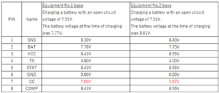
The voltage of each PIN of the BQ2057W during charging caused a large difference in the voltage of the same battery.
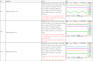
The voltage on CC PIN is so high that the M20 P-Ch MOSFET is just short of Vgs, causing a ripple in the charging current.
Although they are different boards, the voltage of CC PIN is high on the No.1 board, causing a ripple in the battery charging current.
M20 can be turned on firmly, so no ripple is generated.

(1) I recognize that CC PIN is about 1.5V on the datasheet, but the voltage does not drop when the input voltage is as high as 9V, but is there any possible factor?
(2) Although the circuit itself is similar, if there are any possible factors that differ between No. 1 and No. 2, please let us know.

Charging part circuit of devices No1 and No2
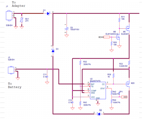


Regards,
Kagawa

  • Hi Kagawa

    Can you tell me a little more about your battery?  It sounds like a dual Li-Ion battery with a capacity of 1000mA.  The typical charge charge voltage will be 8.4V, Constant Voltage charge point.  If the battery voltage is below this point charge will constant current,  set by R33 to 500mA. 

    In the above measurements the battery voltage is below 8.4V (7.78V and 7.73V) and unit should be in constant current phase. We see that voltage drop on R33 is 100mV which is correct for constant current charge phase, about 500mA charge current.

  • Hi Bill-san,

    We are using two 1000mA lithium-ion batteries in series.
    The recognition of a full charge at 8.4 V is correct, and the effective charge current is approximately 550 mA. However, CC PIN did not drop down and a ripple occurred in the charging current.
    I would like to know the factor why the voltage of CC PIN does not go Low.

    Regards,
    Kagawa

  • Hi Kagawa

    The CC pin is an analog output from the Constant Current / Constant Voltage control loop.  It will drive transistor M20, this is a pass element for the linear regulator.  Control loop will adjust CC pin voltage to a level needed for 550mA output or 8.4V.  Expect the voltage on CC pin to vary depending on operating condition.

    BUT you should not see ripple, can you describe or send a scope capture?

  • Hi Bill-san,

    The scope capture is as follows.


    Regards,
    Kagawa

  • Thanks for the additional information.

    The ripple is at a high freq, --- Try adding additional capacitors at output of M20 (Drain), the filter capacitor and battery are isolated by D2 and additional filtering may help.