This thread has been locked.

If you have a related question, please click the "Ask a related question" button in the top right corner. The newly created question will be automatically linked to this question.

LMR36015: Final optimisation questions for maximum operating efficiency

Part Number: LMR36015

Hi,

I've a very small circuit where the LMR36015 (1MHz) is feeding 4.85v into a load. Input current is fixed at 0.5A with a theoretical 20V point, so 10W, but in reality it'll be more like 12-13V. With no load the input voltage can rise to 48V where it is capped by Zener.

I'm using the 1MHz chip and a CoilCraft 4030 10uH inductor (I can't go a bigger foot-print than this). Input capacitance is a close 4.7uH X7R and a 1000uH electrolytic a little upstream. Output is a 22uH X7R and a 220uH tantalium (1 ohm). Ripple is good, not as good as 3x 22uH but board space is very tight and there's no room for more. It's acceptable.


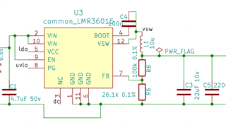
When I ran a test I managed to get 1.82W at the output while I know 2.03W is possible. While I'm not providing the detail for this test here it's another buck sharing the same input and load, demonstrating that the other device is being more efficient.

To find out where any losses are I did an infra-red check. The chip isn't hot by any means, less than 28c with a 200mA load (while the green area is 21c), but shows if I'm to optimise then I need to consider it first.


At 1MHz a 4-30v buck would typically use a 4.7uH inductor. As I'm not drawing more than 0.5A current above an input of 20V, I'm wondering if I'm also better going for this rather than the 10uH recommended by the datasheet. Or, maybe I'd be better sticking with the 10uH and going for the 400KHz chip?

Any other thoughts warmly appreciated!

Andrew

  • Hi Andrew,

    Are you using the FPWM enabled variant? FPWM will switch at constant frequency across load and will consume more quiescent current than a device operating in AUTO mode. That being said you can achieve higher efficiencies at light load with an AUTO mode enabled device. 

    You may be able to find a 4.7uH inductor with a lower DCR than your current inductor which will help reduce the power dissipated by the inductor. This won't change the power dissipated by the IC itself but it will help to reduce the overall power dissipation which may help reduce the overall temperature.

    Regards,

    Harrison Overturf 

  • Hi Harrison,

    I rechecked, LMR36015FBRNXR, which if FPWM. Unfortunately I'm at the mercy of what's available (or was at the time, now neither are).

    With no load the chip is at ambient temperature, so great. That IR picture above is at 200mA output, I'm not sure if diode-emulation would still be enabled anyhow at that current? The inductor shows no relevant heat dissipation, it's all in the chip.

    I observed that I'd omitted the 220nF capacitors on the input side (whoops). I monkey-patched them onto the board and observe no difference, so I may have got lucky there, especially as I'm out of board space.

    I did run the inductor calculations in the datasheet and the input/output current made little difference - it was mostly effected by the input voltage. In 99% of usage the input voltage will be <20V at any output load but I have to consider there's 1000uF capacitance on the input that could be charged to 50V, then a high current output (USB) gets attached and for a brief moment the chip is operating where I expect a 4.7uH may be too low. During this condition lack of efficiency would be fine but if the inductor saturates and could lead to the chip being destroyed then I'd have to stick with 10uH.

    Otherwise I'm not really sure. The datasheet only quotes efficiency figures for the 400KHz variant, which I'd try if I could get hold of a chip. Perhaps my expectations for the 1MHz chip are too high especially considering the internal FET's RDS is relatively high.

    Regards,

    Andrew

  • Hi Andrew,

    The device would likely be switching in PFM mode at the 200mA operating condition for 20Vin, 4.85Vout. 

    To avoid inductor saturation we recommend selecting an inductor with a saturation current rating at least as large as the maximum high side current limit. That way the inductor won't saturate even when the output is short circuited. 

    Figure 10-28 does show an efficiency graph for the case of 1MHz FPWM operation, FYI.

    I made a quick Webench design of this situation, based on the design it looks like the temperature you measured would be expected for the case of 12Vin, 4.85Vout, 20mA, 1MHz FPWM operation assuming 21C ambient temperature. Webench calculates 30C for this condition. 

    Here's the link: 

    https://webench.ti.com/appinfo/webench/scripts/SDP.cgi?ID=64B4B6C14BEE0363 

    Regards,

    Harrison Overturf 

  • Hi Harrison,

    I realised not long after posting the 1MHz graphs are at the bottom. I make it 3-5% less efficient than the 400KHz, excluding trade-offs in inductor DCR, and of course less when I factor that in. 

    That's interesting about the Webench which I've not used before. I notice two things;

    1. you're using a capacitor to adjust phase with the 100k res. I was under the impression for 100k or less the I.C is internally compensated.

    2. you're using a 4.7uH inductor, which I'll swap to all things being considered, but the datasheet equation still wants a 10uH+ inductor at 50v input regardless of the output current. Both the 4.7uH and 10uH inductors I have have available have a saturation point well above the peak. There must be more to it or we'd all be using 0.1uH inductors! - I'm wondering what happens at 50v input when 4.7uH is used over 10uH?

    Many thanks for taking time to respond.

    Andrew


  • Hi Andrew,

    The LMR36015 is internally compensated. The feed forward capacitor (Cff) placed across the top feedback resistor is used to as a way to boost phase margin and increase transient performance. For more information on the role of Cff please see the following app note: slva289b_selectingCff.pdf

    With regards to the inductor selection, equation 4 in the datasheet is derived from the inductor voltage equation: V = L*(di/dt) 

    For a given input voltage and output voltage condition, and a given switching frequency we can select an inductance value to achieve a desired inductor current ripple. So in the case you presented above, a 4.7uH inductor will have more current ripple than the 10uH inductor assuming all the other conditions remained the same. I estimate 438mA current ripple for the case of 10uH inductor and 932mA of inductor current ripple for the 4.7uH inductor. From an efficiency perspective more current ripple will mean more AC core losses in the inductor, but lower inductance will usually result in lower DCR for the same package size so that tradeoff will need to be considered. 

    I wouldn't recommend using a 0.1uH inductor because the ripple would be too large and result in the converter becoming instable, see equation 5. 

    Hopefully this helps. 

    Regards,

    Harrison Overturf 

  • Hi Harrison,

    What I mean by 0.1uH is there has to be a point where for the given frequency/voltage/current the inductance can't go any lower. If I drop from 10uH to 4.7uH and neither are saturated, and the input voltage rises to 50V while nominally having only 100mA out, but very briefly could be 1A out while the input capacitor discharges (the input voltage would sag from 50V to say 10V very quickly under this output current) then the question is whether 4.7uH is still enough. The datasheet equation thinks not.

    Regards,

    Andrew


  • Hi Andrew,

    I'm confused at what operating conditions you are evaluating whether 4.7uH will be enough. 

    The part should be able to operate with the 4.7uH inductor so I'm not sure how you're coming to that conclusion. 

    Using equation 5 I calculate 1.3uH = LMIN (for VOUT=4.85V, fsw=1MHz). 

    Regards,

    Harrison Overturf 

  • When I calculated it I came out at about 16uH.

    The operating conditions (excluding ripple which doesn't have to be too strict as USB).

    Output voltage = 4.85V (I'd use 5V but the PG trigger is too high).

    1. nominal condition, peak input voltage - 15V input, 0.5A output
    2. standby condition, max input voltage - 48V input, 50mA output
    3. nominal condition, standard input voltage - 6V input, 1A output
    4. brief connect condition - 48V input, 1A output

    So it is condition (4) I'm querying if a 4.7uH inductor will be enough. This condition is caused by a 1000uF input capacitor which will discharge and the input voltage will sag to reach condition (3).

    I believe 4.7uH will be most appropriate for condition 1-3, but question for condition 4 what will happen. 

    When I ran the calculations both condition 2 and 4 indicated an inductor above 10uH. I could tell by playing with the values that the input voltage and frequency set the majority of the required inductance, not the output current (which determines saturation rather than inductance).

    Regards,

    Andrew


  • Hi Andrew,

    Thank you for clarifying the information above.

    We typically recommend sizing the inductor based on the worst case operating conditions. Since you have calculated 10uH for conditions 2 and 4 then you may want to select 10uH. 

    For condition 4, I calculate 920mA inductor current ripple when using the 4.7uH (for Vin=48V, Vout=4.85V, fsw=1MHz). As the input voltage increases from condition 3 to 4 the inductor current ripple will increase since the output voltage and frequency will remain constant. The part will continue to regulate the output to 4.85V and provide the output current demanded by the load which is 1A in this case. We can calculate the expected peak inductor current to be 1A + (0.92A/2) = 1.46A which is below the short circuit current limit of the device. If you use the 10uH, the inductor current ripple will be close to 430mA. 

    Regards,

    Harrison Overturf 

  • Excellent response Harrison, thank you. 

    Condition 4 is only for the briefest of moments. Let's say there was a short applied at this input voltage would the chip survive? I imagine it skips and goes out of regulation. This would be quite acceptable because a USB connecting at this voltage (when the machine is already turned on - they 99.9% normally connect when it is off) is very unlikely.

    As you indicate there doesn't appear for the given conditions to be any reason to go with 10uH which will be less efficient than the equivalent sized 4.7uH with lower DCR. I'll make that final if you confirm it I haven't missed anything!

    I have two other questions around this chip and you seem best placed to answer them:

    1. I'm ready to go to production but need a minimum 250pcs to make it viable. The part is back in stock but restricted to 50pcs. Is there any means to order more, perhaps by verifying I'm not a reseller intending to flip them!? I've tried speaking to online help but they're just quoting what the TI website has on it.

    2. I've found USB and the PG to be tricky. The buck supplies a MCU and I share the power with USB by a low side NMOS. When the USB connects the buck can't keep up and the voltage sags resetting the MCU. I've stuck a 220uF 6.3v tantalum in with the 44uF X5R's to limit the insertion shock, which works.

    Next, with so much variance between USB devices and a saggy input power supply I've compromised on a 4.85v and not 5.00v output, which roughly means the PG triggers around 4.4v, otherwise I've found the PG triggers for many USB devices. The falling VPG-LOW-DN is specified as 90-95% (typ) 93% but there's also a VPG-HYS of 2%. This I don't understand does it mean the actual typ PG low point is 91%?

    Thanks again,

    Andrew


  • Hi Andrew, 

    Thanks!

    If a short occurred at the input I would be concerned about the output capacitors discharging through the HSFET body diode which would cause damage. This can be prevented with a diode connected from the Vout node to Vin of the IC. See Table 4-2 in the functional safety documentation: LMR36015-Q1 Functional Safety, FIT Rate, Failure Mode Distribution and Pin FMA (Rev. C)

    Based on our discussion so far I think the 4.7uH can work here. 

    In terms of ordering more, we can't change the order limit due to the tight supply unfortunately. 

    To your PG question, I'll refer you to Figure 9-2 and 9-3 as these give you the best visual explanation of how the PG functions. The PG parameters provided in the EC table give you the levels at which the PG output will fall low representing that the output voltage is out of regulation. The hysteresis value is applied to both the rising and falling levels. So if the PG output is asserted when the output voltage is at 95% of the set point then it needs to fall to 93% of the set point for the PG output to go low. 

    Regards,

    Harrison Overturf 

  • Hi Harrison,

    Sorry I wasn't clear, that's a short at the output. The input can't be shorted.

    It looks like I have a while to wait with this chip then. Only been two years so far... sigh. :(

    Regards,

    Andrew

  • Hi Andrew,

    Thanks for your patience regarding supply. 

    Short at the output will result in the device operating in hiccup mode until the short is removed. This is described in section 9.3.3. 

    I'm going to close this thread for now. If you have any more questions related to this topic, post a reply to this thread otherwise feel free to generate a new post. 

    Regards,

    Harrison Overturf