This thread has been locked.

If you have a related question, please click the "Ask a related question" button in the top right corner. The newly created question will be automatically linked to this question.

UCC5870-Q1: OUTH keep high for a long time

Part Number: UCC5870-Q1

Dear team,

Could you please help answer below two questions? Thanks!

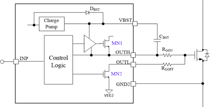
1. Could you please tell me whether our Bootstrap function can support OUTH remains high for 2 hours? In my understanding, the bootstrap cap needs to be charged during OUTH off time, but I don't see input PWM minimum off time requirement in the specs, so I am not sure whether the C_BST cap can keep high voltage for two hours.

2. Do we have any recommendation for C_BST cap package?

Thanks & Best Regards,

Sherry

  • Hi Sherry,

    Thank you for posting to E2E.

    Majority of the time the bootstrap capacitor will be the source that provides the voltage to the internal pull-up NMOS during turn-on transients. When this capacitor does not have enough time to charge during high duty cycle conditions the gate driver will engage an internal charge pump to supply that voltage.

    Now this charge pump is there to handle low frequency high duty cycle conditions, but I don't believe we considered a condition where the output would remain high for 2 hours. I will discuss with my team if keeping the output high for 2 hours will have any problems with the gate driver. In the meantime could you help me understand this condition better.

    • What is the end equipment for this opportunity?
    • Why does the customer need to keep the output high for 2 hours?
      • Is this fail safe condition or what type of operating mode will the system be in that needs the output high for 2 hours?

    Best regards,

    Andy Robles

  • Hi Andy,

    Thanks for your reply!

    For your questions, I will update to you tomorrow.

    For question 1, please help confirm with your team.

    In addition, for question 2, Do we have any recommendation for C_BST cap package?

    Thanks & Best Regards,

    Sherry

  • Hi Sherry,

    There is not special requirement on the bootstrap capacitor. The customer should just ensure that the capacitor is rated for greater than or equal to 6.3V to account for capacitance de-rating.

    For the 2 hour OUTH HIGH requirement I want to make sure we understand the customers use case.

    If they need to keep a SiC FET or an IGBT ON for long a long duration of time then there should be no issues. This is due to the fact that once the SiC FET or IGBT is turned ON the power switch will no longer pull any current from the gate driver to keep the device ON.

    The gate driver is not intended to drive a DC load. Pulling a constant current through the gate driver could result in damaging the device.

    Let me know once you get more information from the customer on the use-case.

    Best regards,

    Andy Robles

  • Hi Andy,

    Thanks for your reply!

    My customer has more questions about this charge pump as below,

    1. OUTH continues to be at a high level. In order to ensure that MN1 is turned on, does the Charge Pump need to work to maintain it? In my understanding, the charge pump has to work. Cbst will discharge with internal resistors, so the voltage on Cbst will decrease. When the voltage decrease to one value, MN1 can't turn on, right? But this discharge takes a long time, so it can keep OUTH to be high level for two hours.

    2. The wiring of MN1 is disconnected in below block diagram, where should it be connected?

    3. If we use 2kHz switching frequency. What is the max duty cycle? For example, 80% or even larger?

    The customer use case background is as below,

    As shown in the figure, our system considers most of the working conditions ASC (Active short Circuit) as a safe state.

    1. Generally, the low side SiC FET is in ASC working conditions(S4/S5/S6 OUTH is always high level). Generally, many vehicles will maintain this state as long as the low-voltage KL30 is turned on, and the duration is not limited (may last longer than 2 hours).

    In addition, under the failure condition, it will also enter the low side(S4/S5/S6) ASC according to the fault condition, and the duration depends on the working conditions of the whole vehicle (for example, when the vehicle fails on a long downhill, it will also enter the low-side SiC FET ASC protection state).

    2. Some customer request that the minimum duration of ASC is 30 minutes(motor with current).

    In summary, considering the application conditions of the whole vehicle, S1-S6 of below topology need to maintain a continuous high level state, and the following conditions need to be met when maintaining a continuous high level open state (the maximum operating temperature of the chip)
    1: Be able to provide a sustained high level to turn on the SiC
    2: It cannot cause the driver chip to fail. 

    Thanks & Best Regards,

    Sherry

  • Hi Sherry,

    Andy is OoO on international travel; I will try to help address your questions while he's out.

    1. OUTH continues to be at a high level. In order to ensure that MN1 is turned on, does the Charge Pump need to work to maintain it? In my understanding, the charge pump has to work. Cbst will discharge with internal resistors, so the voltage on Cbst will decrease. When the voltage decrease to one value, MN1 can't turn on, right? But this discharge takes a long time, so it can keep OUTH to be high level for two hours.

    As stated in the datasheet, "for slow switching frequencies at high duty cycles the external capacitor may not be able to charge enough during the OUTH off time to supply the gate drive for the entire on-time. In these conditions, the charge pump circuit is used to hold the voltage across the bootstrap capacitor." In a normal bootstrap configuration the bootstrap capacitor will discharge, but with the integrated charge pump of the UCC5870-Q1, we don't have that problem.

    2. The wiring of MN1 is disconnected in below block diagram, where should it be connected?

    It should be tied to VCC2, which is the source of the OUTH current and high gate voltage.

    3. If we use 2kHz switching frequency. What is the max duty cycle? For example, 80% or even larger?

    The device supports 100% duty cycle thanks to the charge pump.

    Regards,

    Audrey

  • Hi Andrey,

    Thanks for your reply!

    The device supports 100% duty cycle thanks to the charge pump.

    It seems that the charge pump is independent of the Cbst, so it should have no relationship with the switching frequency. 100% duty cycle means OUTH always high without off time, so our device can always high for any period, right? 

    Thanks & Best Regards,

    Sherry

  • Hi Sherry,

    Yes, you are correct.  100% duty cycle implies a DC signal.  This E2E Post shows a 100% duty cycle waveform of the UCC5870-Q1. 

    Thanks,

    - Aaron Grgurich