This thread has been locked.

If you have a related question, please click the "Ask a related question" button in the top right corner. The newly created question will be automatically linked to this question.

TPS61094: Dual power source - cascade or parallel connection?

Part Number: TPS61094

Hi,

I am designing a back-up power circuit including a primary battery and a supercapacitor.
Main use case for the supercap is to supply power while replacing the battery.
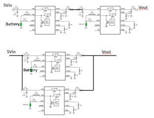
Current design is a cascade: first stage running on battery and second on supercap.

Now the leakage current of the supercap consumes a lot of juice from the battery.
Is there a better way to design, e.g can two TPS61094 chips be connected in parallel?
Configuring different output voltage decides priority?

  • Hi Jouko,

    Thanks for reaching out on E2E. Could you please share your sch or block diagram, because of I am a little confusing about your current design? Typically, the battery and backup super cap is designed as below sch (Vin is battery voltage):

    Best Regards,

    Eric Yue

  • The presented typical sch has a draw back: the leakage current into the supercap takes 5-10uA from the battery. The actual load current in my case is 10uA so we are losing half of the energy available from the battery.
    We have 5V power rail when device is running. When powered off, power comes from battery. While battery is being replaced, we want to have energy from supercap. The idea is to use two chips in cascade/parallel, but now the mentioned leakage current issue must be solved.

  • Hi Jouko,

    I will check with our system engineer to check if there is any possible solution to solve the super cap leakage current. As long as I know, this leakage current might be one disadvantage of TPS61094 design. I will update the result later. Thanks for your patience.

    Best Regards,

    Eric Yue

  • Hi Jouko,

    I just got the feedback. May I check whether the used battery is chargeable or non-chargeable? If non-chargeable, using one diode and set battery and super cap in parallel is ok.

    Super cap's leakage current will be lower if lower terminal voltage is selected. For example, for 3 F cap, working at 2.0 V can reduce the leakage current to 20 %, the leakage current: 25 ℃: 1 μA (5 μA * 20 %), 40 ℃: 2 μA. Do you think this method make sense for you?

    Best Regards,

    Eric Yue

  • We are using non-chargeable battery.
    One piece of information I am looking for is the snooze mode. If the circuit is set for 3.6V output (boost mode) and there is higher external voltage (3.8V) connected to the output, the chip goes to snooze mode and then the device goes into "sleep status". Data sheet says that it consumes "less current". However, I did not find more detailed information of "less current"?

  • Hi Jouko,

    Please refer to 7.4.5.3.3 in datasheet of snooze mode. Snooze mode will work in burst mode to further reduce consumed current and improve system efficiency. Because the load is lighter, so the chip's sleep time is longer in snooze mode so that the consumed current for long time is decreased. 

    Best Regards,

    Eric Yue