This thread has been locked.

If you have a related question, please click the "Ask a related question" button in the top right corner. The newly created question will be automatically linked to this question.

TPS74801: TPS74801RGWT SS voltage Problem

Part Number: TPS74801

Hi team!

Help!

Recently I have designed a new board using TPS74801RGWT, the following picture shows the schematics.

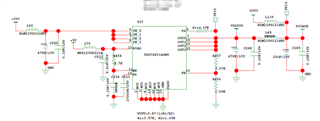
Actually this LDO was a backup circuit, I did NOT solder L48 for use, that means this TPS74801 was almost no load. During my debug work on these boards (13 pieces in total), I found TPS74801 could not output 2.5V voltage normally on two boards, while on the other 11 boards this LDO worked OK. Then the following test/change were done:

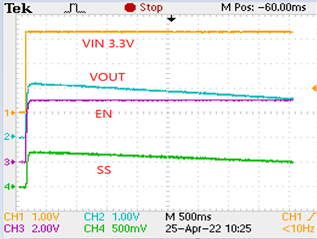
1. Test the SS, EN, IN, OUT voltage during power up on failed board, the SS voltage would get down slowly after charged to about 0.8V. While on a board with good output, the SS voltage would maintain 0.8V after power up.

2. Remove SS capacitor C523 and retest all four voltage above, SS voltage still getting down after power up but with less time to 0V. Then enlarge SS capacitor C523 to 47nF, and SS voltage still getting down but with more time to 0V.

3. Solder a resistor between output and GND to enlarge the output current to 125mA, then power up, and found SS voltage still getting down.

4. Connect the SS pin of TPS74801 to a 0.8V power source from outside, the failed TPS74801 would output 2.5V normally.

5. Replaced one failed TPS74801 in one circuit board with a brand new one and the new one worked well while this did not work in the other circuit board.

Besides, I checked the solder condition and found it seems OK. And all the temperature was around 25℃ during these experiments.


Now I have some questions here--

  1. Can you help to review my design, is there any problem according to the schematic shown above?
  2. How could I confirm whether the chips were OK, I somewhat doubt there might be something wrong with this batch of TPS74801.
  3. According to the experiments on the SS pin, the problem seems to related to the soft-start discharge block inside the chip, could you help to explain more details about the mechanism of the SS pin work inside?
  4. Any other suggestions on debugging?
  • Hello,

             Baring a couple of aspects, your schematic looks fine. The feedback resistors values shown in the schematic are 1.57KΩ and 1.69KΩ, and with these resistor values I can't see how the output voltage value will equal 2.5V. Could you also clarify the role of L139 in the schematic? If I understood correctly, your output voltage was stable at the desired value after the device was replaced with a new device. If so, it's likely that the older device was faulty. It is unlikely that a whole batch of devices would be faulty, since every device is tested before they are released to the market.  The SS cap essentially reduces the magnitude of inrush current by controlling the ramp rate of rise of VOUT during startup. The following App Note describes this in a bit more detail. Thanks!

    Regards,

    Srikanth

  • Hi, Srikanth

    Oh, poor image resolution, the feedback resistor R457 is 3.57kΩ. Power net VCCAUX can connect to 2.5V or 3.3V, here L139 and L48 are used to choose power supply,  L48 was not soldered actually, so TPS74801 is almost no load. And for my fifth test/change, I need to explain more, two boards were found have TPS74801 circuit abnomal, I replaced both of the two boards' TPS74801, on one board the LDO would output 2.5V as expected, while the other board still could NOT have normal output. One more information I need to emphasize, after I supply a 0.8V power to the faulty LDO from outside, the LDO would have stable output value.

  • Hello Qi,

                  If L48 is not in place, then I do not see any schematic issues. It does appear that the original device (for which external 0.8V supply was needed) is damaged. This could have happened during Packaging, handling, testing, transportation etc. It would be difficult to isolate the reason. It is rather unlikely that a whole batch of units would be damaged. It is good to know that with a brand new device the board was providing the desired output voltage without the external 0.8V supply to the SS pin. Thanks!

    Regards,

    Srikanth

  • Hi Srikanth,

    Thanks for your replay.

    Is there any easy way to check the LDO? There are more than 300 pieces in our warehouse, I need to find out the faulty LDOs ...... sigh

  • Hello Qi,

                  Unless the parts are physically damaged, there is no simple way to deduce if they are fully functional.....sorry. 

    Regards,

    Srikanth

  • Hello Srikanth,

    Thank you for your reply.