This thread has been locked.

If you have a related question, please click the "Ask a related question" button in the top right corner. The newly created question will be automatically linked to this question.

TPS630250: Buck/Boost Converter Circuit

Part Number: TPS630250

Hi,

I am using this TPS630250RNCR to Buck/Boost the voltage of a 1S lipo cell. I attached a link to Cell at the bottom. In my first design, there were some unknown issues that still I didn't figure out.

In the new design, I have the following questions.

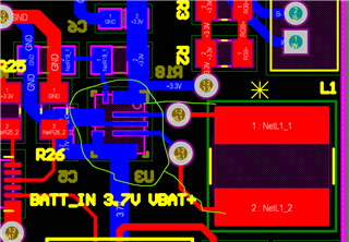
What should be the track width for inductor connection with IC? It is close enough placed but I need this information. I attached a picture of the current situation.

Note: LOAD is less than 1A at the output of the circuit

  • Hi  Ali

    the RMS current of these traces should be about 1A during BUCK working. during boost working, it is depend on the voltage of input and output. but i think it should be less than 1.5A. so, if you can set the width of these trance 20mil least. that should be ok.

    also, i think the layout is not a good one, could you take the layout example in the datasheet as ref?  espically the power stage.  i think it will be much better.

    Regards

    Tao