Hi team,
I'd like you to review my schematic. The schematic and Calculation sheet I will send the privet message.
Sincerely.
Anoop Varma
This thread has been locked.
If you have a related question, please click the "Ask a related question" button in the top right corner. The newly created question will be automatically linked to this question.
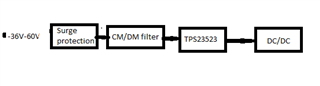
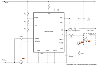
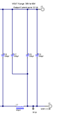
Hi team,
I'd like you to review my schematic. The schematic and Calculation sheet I will send the privet message.
Sincerely.
Anoop Varma
Hi Anoop,
Thanks for reaching out. Please share the schematic and design calculator.
Hi Avishek,
The below system input voltage is 60V max, input surge protection circuit is designed for 120V(Vclamp 120v->AK10-066C). My question is whether 100V MOSFET(Gate 1 Q1) is enough for this circuit.
Hi Anoop,
Thanks for reaching out. Are you talking about which MOSFET, Q1, Q2, or Q3?
Hi Anoop,
100 V VDS rating of Q1 is fine.
Please see below screenshot to select Q2.
Hi Avishek pal ,
Thanks for Replay,
1)Which one is RCC resistor ?
2 )Our under-voltage requirement is 36V and OV voltage 60 V, But your calculator mentioned it is UV 39V and 58V.Can we change?
Hi Anoop,
Please see the responses in the order of your queries.
1) RVCC is the resistor connected between RTN and VCC of TPS23523.
2) You can change according to your design specifications. I had not modified those cells.
Hi Avishek pal
Thanks for the replay,
1)what is the meaning of (Ti calculator column 21) Target current limit.
Our system 1st turns on the BMC section, it is taking 4A, thereafter other section enabling. If so, can we set the 4A target current limit?
2)PGB pin Can we connect directly to Regulator enable?
3) Is it necessary or not LC filter in output? ( we have CM/DMfilter on the input of DC-DC regulator )
Hi Anoop,
Sorry for the delay in getting back to you. Please see the responses below in the order of your queries.
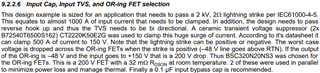
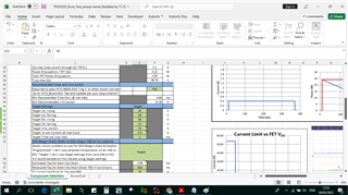
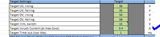
1) Target current limit should be at least 10% more than the maximum steady-sate DC load current based on the minimum input voltage and maximum output power.
2) No... It can't be. Please refer to the section 9.2.2.10 Power Good Interface to Downstream DC/DC in the TPS23523 datasheet for more details.
3) Then, it's not necessary.
Hi Avishek,
Thanks for your support. The updated schematic will send for review.
If I get back to you on Monday, is it fine for you? I will on leave from tomorrow to Sunday.
Hi Anoop,
Please share the latest design calculator based on which the schematic has been developed.
Hi
Hi Avishek,
PFA, The design calculations are the same as those you modified in the first review. Please check private chat.
Hi Anoop,
Thanks… I will share the review comments by today end of the day.
Hi Anoop,
Sorry for the delay. I need some more time to review the schematic. I will get back to you end of this week.
Hi Anoop,
TPS23523 schematic looks fine to me. However, it seems that the component values are not updated as per the design calculator.
Hi Avishek,
The below yellow color marked part I changed as per your previous command.
Hi Anoop,
You should make the values of the "Selected Components" as per the "Computed Components".
Hi Avishek,
I changed,
what is "Target inrush current(at max count)" mean, it is showing 0.4A only.
Hi Anoop,
This is the current by which the output capacitors will be charged.