This thread has been locked.

If you have a related question, please click the "Ask a related question" button in the top right corner. The newly created question will be automatically linked to this question.

BQ24070: question about possible current problem

Part Number: BQ24070
Other Parts Discussed in Thread: TL1963A

greetings to the experts of Texas Instruments and members of the forum.

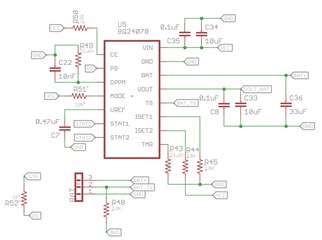
The power supply of our tracking device is designed as follows:


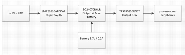
the processor (the system load) is made up of a wifi module which runs an operating system (I don't think it's very relevant at the moment)

If I connect power to the device without connecting the battery, the module starts without problems.

but if I connect a battery (discharged or partially charged) the wifi module restarts at a time of high consumption (when the wifi module picks up the wifi network). This reboot happens over and over and over again until the battery is charged, only until this moment the module starts correctly.

In that order of ideas my questions are the following:

1. According to the datasheet of the BQ24070, the regulator always gives priority to the consumption of the load, and the excess current is used to charge the battery.

Is it possible that I need to adjust some component so that it always delivers the maximum current to the load?

2. In a previous version, the TL1963A regulator was used with an output of 1.5A fixed at 3.3v, with this regulator this reset problem did not occur, but this is a linear regulator and the regulator used in the new design is switched (TPS630250RNCT).

Is it possible that the combination of the BQ24070 and the TPS630250RNCT has a problem?

3. One theory (which I would like you to clarify for me) is that the problem is that the current supplied by the BQ24070 is not enough for the TPS630250RNCT regulator and this is reflected in the output current.

If my theory is correct, can I somehow bypass the current from the output of the LMR23630AFDDAR regulator to the input of the TPS630250RNCT regulator?

Note1: With the oscilloscope I have monitored the output voltage of the TPS630250RNCT regulator to see if the voltage dropped and generated the reset of the Wi-Fi module, but there are no voltage drops when the reset occurs.

  • Hi Jose,

    This is very interesting, I don't believe I've heard of this repeated restart while battery is charging when our chargers are used in a wi-fi related application. Would you be able to share the battery charger portion of the schematic? I'd like to see how you've configured the charger to ensure everything is optimal. 

    To answer your questions and to confirm your statements:

    1. According to the datasheet of the BQ24070, the regulator always gives priority to the consumption of the load, and the excess current is used to charge the battery.

    Is it possible that I need to adjust some component so that it always delivers the maximum current to the load?

    You're correct that the BQ24070 OUT pin power is prioritized over the battery charging. Based on your block diagram it looks like you have the charge current set to 200 mA. As long as your input current is set for 200 mA + current load at the output, the prioritization on the OUT load will happen automatically.

    In a previous version, the TL1963A regulator was used with an output of 1.5A fixed at 3.3v, with this regulator this reset problem did not occur, but this is a linear regulator and the regulator used in the new design is switched (TPS630250RNCT).

    Is it possible that the combination of the BQ24070 and the TPS630250RNCT has a problem?

    I can take a look in more detail if needed but I don't expect this to be a problem unless the input current limit of the BQ24070 is set below the required current that the TPS device will be outputting.

    3. One theory (which I would like you to clarify for me) is that the problem is that the current supplied by the BQ24070 is not enough for the TPS630250RNCT regulator and this is reflected in the output current.

    If my theory is correct, can I somehow bypass the current from the output of the LMR23630AFDDAR regulator to the input of the TPS630250RNCT regulator?

    Yeah this is a suspicion I have as well and it'd be great if you added a schematic so I can confirm or do some testing on my end. 

    You most definitely could bypass the current by instead having the LM device power the TPS instead. You'd essentially connect the BQ24070 and the TPS device in parallel at the output of the LM device. 

    Again, as long as the current being supplied is sufficient, this should work but even then the BQ should also enter supplement mode and allow the current from the battery to add to the load if the ILIM is possibly too low.

    Note1: With the oscilloscope I have monitored the output voltage of the TPS630250RNCT regulator to see if the voltage dropped and generated the reset of the Wi-Fi module, but there are no voltage drops when the reset occurs.

    This is what I'm most interested in. If you're not seeing an voltage drops on the TPS device, it's odd that the Wi-Fi module would reset unless it's a current issue which can happen as Wi-Fi packets transmit or are received results in higher current transients. Would you be able to monitor the current when this occurs?

    Are you able to monitor the STAT1 and STAT2 pins and share a waveform capture of these when you see the Wi-Fi module reset?

    Best Regards,

    Anthony Pham

  • Hi Anthony,

    thanks for your quick response,

    This is the schematic circuit of the BQ24070 battery charger, I will do the tests you gave me and as soon as I have the results I will publish them.

  • Hi Jose,

    At first glance, I don't see any issues with the schematic. Looking forward to seeing your test results.

    Best Regards,

    Anthony Pham