This thread has been locked.

If you have a related question, please click the "Ask a related question" button in the top right corner. The newly created question will be automatically linked to this question.

UCC5350: UCC5350MC schematics review for SiC FET

Part Number: UCC5350

Hi team,

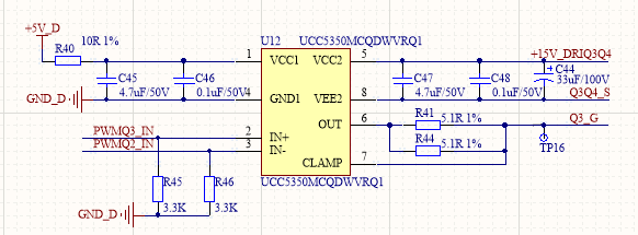
Below is the schematics to drive Infineon SiC CoolMOS, which VEE2=0V is enough for switching off. Is there need any protection circuit such as TVS clamp here?

Thanks.

  • Hi, Jerry,

    Ni hao!

    Some recommendations:

    1. Make sure C46 and C48 are within 2 mm of the IC pins when doing the layout 
    2. Place R41 and R44 close to the CoolMOS gate when doing the layout 
    3. Add pads for an RC LPF on IN+ and IN- in case they run into noise issues

    Placing a pad for a TVS isn’t a bad idea, as long as you make the gate loop as tight as possible. Added stray inductance in the gate loop makes it harder for the driver to accurately control the gate of the power device. 

    I would like to review their layout before they send their board off for build. 

    Best regards,

    Don