This thread has been locked.

If you have a related question, please click the "Ask a related question" button in the top right corner. The newly created question will be automatically linked to this question.

UCC29002: UCC29002+TPS2412 for Current Sharing and Redundant Solution

Part Number: UCC29002
Other Parts Discussed in Thread: TPS2412

Hi, 

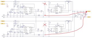
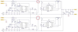
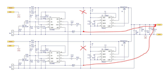
 I am designing a power supply module with universal- AC input and 100W, 28V output. I have a paralleling requirement  for this AC-DC power supply, which means if needed user can parallel these 2 to 3 modules together to increase the overall power output or to increase the reliability of the power supply modules.

In order to share the load equally among the power supply modules, I came across UCC29002 load share controller ic, this can fulfill the load share requirement for 28V output voltage application right? 

but i also have a hotswapping requirement for N+1 modules parallel redundancy solution. for this requirement  I could see  UCC29002+TPS2412 , this can fulfill  hotswapping requirement right?

And this AC-DC power supply should support Remote sensing to compensate for maximum of 0.5V(0.25Vin each output lead) difference in voltage between load and power supply module.

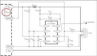
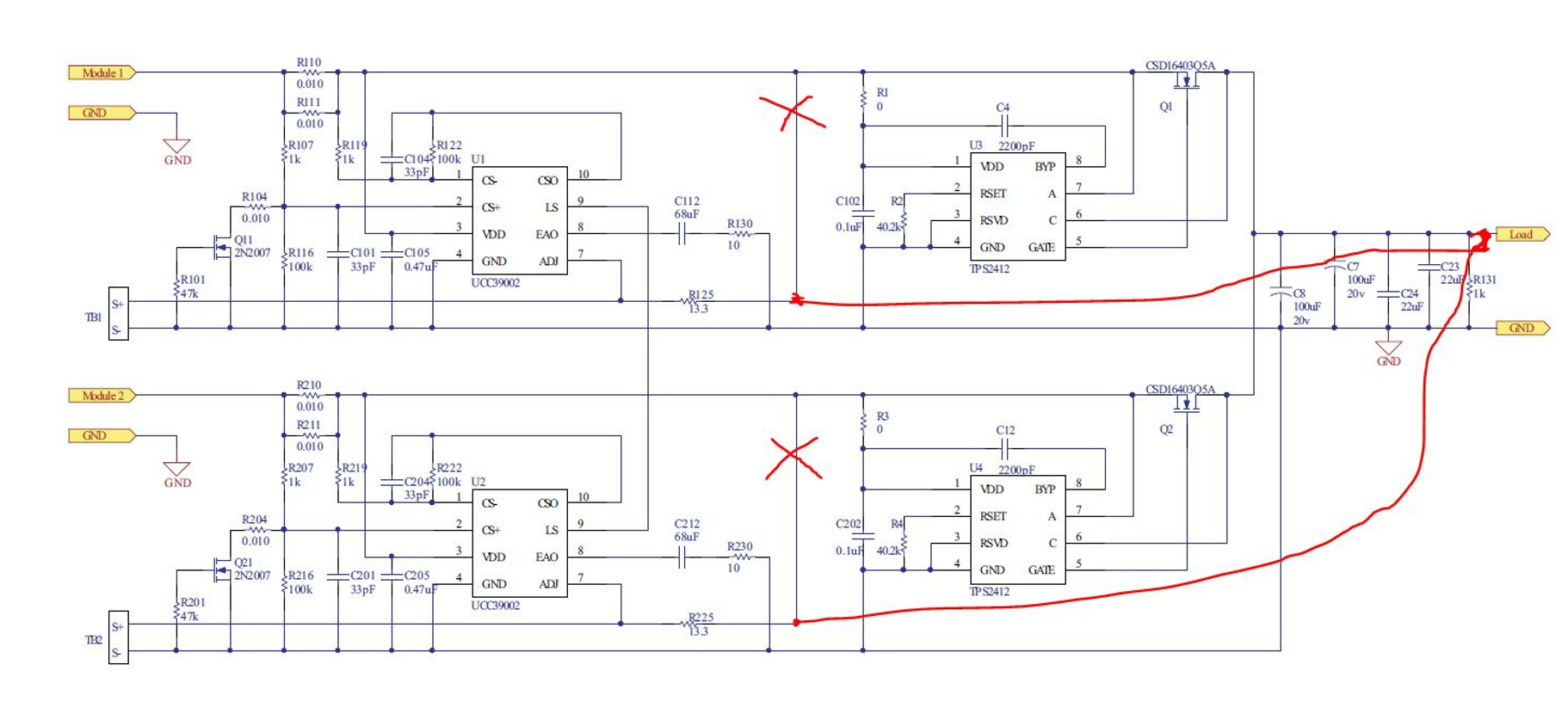
So to compensate this lead length drop, sense+ and sense- pins of power supply are normally should connect at load point. but when i see the application note of current sharing in redundant systems using UCC29002+TPS2412   +sense pin is connected to Vout through Radj resistor before oring Mosfet. please see in below screenshot.   


here is my questions with respect to +sense pin connection.

1. if we connect +sense pin before ORing mosfet, how mosfet drop and lead length drop will get compensated?

2.can we connect this +sense pin at load point to maintain the precise load regulation at the load point?

3. is there any other problems if we connect +sense pin at load point as shown in below figure?

other question with respect to 28VDC output voltage level.

1. I could see from the datasheet of UCC29002 and TPS2412 maximum vdd can support to 15Vdc. i have seen high voltage application figure for ucc29002 load share ic.is there reference design for this selection transistor and bias resistors?

2.same way is there any reference guide document for TPS2412 controller also for 28VDC output voltage level? 

I request you to kindly help me in proceeding further to use this combination of IC's with respect to my requirements.

Thanks.

Best regards,

Thirupathi. A

  • Hi Aluka,

    thanks for your interest in UCC29002. See below my comments for your question.

    1. UCC29002 can be used in 28V output application, you can follow Figure in the datasheeet for high voltage application.

    2. UCC29002+TPS2412 can be used for hotswapping.

    3. in order to compensate the Oring mosfet voltage drop, you canconnect the sense+ to the load point.

    4.Yes, no influence on load regulation.

    5.I do not see any problem for your connecting.

    6.Max idd is 10mA and max Iadj is 6mA. So please select Rbias for at least 10mA. and at least VCE>28V, max current should be higher than 6mA(suggest to select at least 40V rating transistor) . Unfortunately there is not reference design for high voltage application available for you.For the external circuit, please follow the calculator. you can download in through below link:

    https://www.ti.com/product/UCC29002?keyMatch=UCC29002#support-training

    7. I am not familiar with TPS2412, please create a separated post for TPS2412 high voltage application.

  • Hi David,

    Thanks for your technical confirmations on connecting the +sense pin at load point.

    As per the below image if we connect both  power supply modules +sense point at load, for example, if one power supply module output gets shorted, what is the impact on other power supply module due to this short circuit. can you please put your thoughts on this point or any other faults happen in any power supply module?

    And one more question regarding the power supply module internal Rsense resistor as per the below image.

    1.I have seen in your math cad/excel tool Rsense measured/selected as 200ohm.what if this value is too high or high impedance resistor(in ohms)?

    2.Is it mandatory to use Rsense resistor in power supply? if yes any calculation method is there? because i could see this Rsense  value is also a deciding factor of Radj resistor o UCC29002.

    i will create a separate post for high voltage application of TPS2412 IC.

    thanks.

  • Hi Aluka,

    if one power supply output get shorted in the system, since both the two power supply output connects to each other together, the one that do not get shorted will working at pretty heavy(usually if there is constant current mode, it would ouput constant current) load. Please confirm whether at this condition the one that do not get output shorted do not trigger the OCP protection or any other over load protection.

    The Rsense is in parallel with Radj, in real application, usually Rsense should be very high for example ten times of Radj.  So if it is hard to test Rsense, you can set a very high value(Mohm) to do the calculation.

    it is not necessary to use Rsense, I mean just set as high as possible.In this way Rsense do not influence the Radj calculation.

  • Hi David,

    Thanks for your reply.

    I understood if both the power supplies connected together at load, then one gets shorted other will takeover and may trigger OCP protection.

    but as per my below figure we are using ORing FET  in between power supplies and load right? but +sense pin of both power supplies only connected together at load to compensate the drop of ORing FET and any lead length drop.

    so if one power supply output get shorted, then ORing FET will open of this shorted power supply and other power supply will take full current with respect to the load.

    from the above explanation my question is there any impact on other power supply due to shorted output power supply? since both two power supplies +sense pin connected at load point? hope you understood my question.

  • Hi Aluka,

    as I mentioned in the previous post, the one that do not get shorted will take full current, and the one that get output shorted trying to increase the voltage to share the current(even though it can not boost the output voltage), so the system is working at a un-balanced current share condition. I do not see any other influence on it.